
Centrifugal ventilator for aero-engine

An aero-engine and ventilator technology, which is applied to engine components, engine lubrication, separation methods, etc., can solve the problems of large lubricating oil consumption and achieve reasonable pressure drop, high separation efficiency, and good manufacturability

Active Publication Date: 2019-07-30
CHINA AVIATION POWER MACHINE INST
View PDF6 Cites 1 Cited by
  • Summary
  • Abstract
  • Description
  • Claims
  • Application Information

AI Technical Summary

Problems solved by technology

[0006] In order to solve the problem of large lubricating oil consumption under the condition of relatively large ventilation volume of small and medium-sized aero-engines, the purpose of the present invention is to provide a ventilation device for lubricating oil systems installed in the accessory transmission case of aero-engines, which solves the problem of the current small and medium-sized aero-engines. The problem of large oil consumption under the condition of large ventilation volume

Method used


Image

  • Centrifugal ventilator for aero-engine
  • Centrifugal ventilator for aero-engine

Examples


Embodiment 1

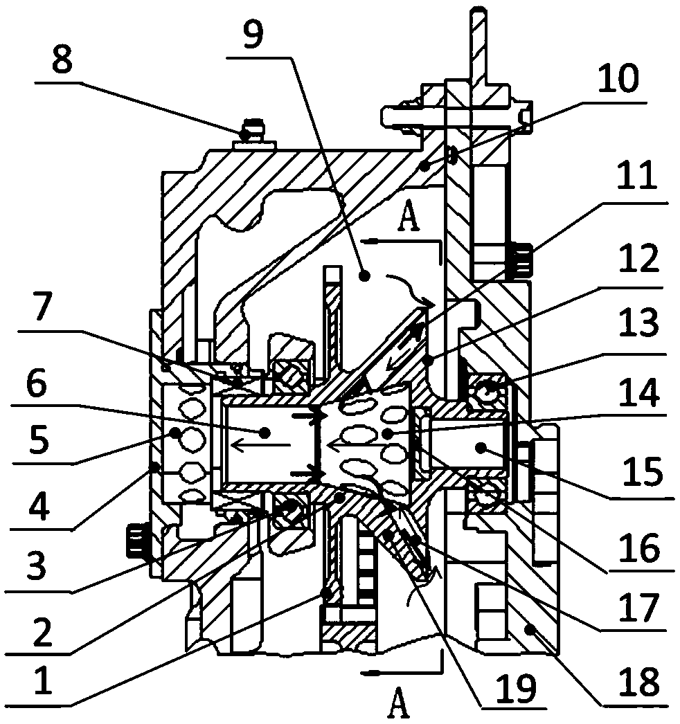
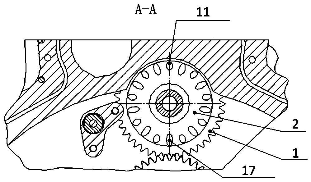
[0024] see figure 1 and figure 2 , an aero-engine centrifugal ventilator is set in the aero-engine accessory transmission casing, and is integrated with the gear 1 in the accessory transmission casing on the same gear transmission shaft 2; the two ends of the gear transmission shaft 2 are respectively provided with The first rolling bearing 3 and the second rolling bearing 13 of the transmission shaft 2; the gear transmission shaft 2 is a hollow structure, and the center of the gear transmission shaft 2 includes three coaxial holes: a central straight hole 6, a central tapered hole 14 and a transmission shaft hole 15, and the central cone The hole 14 is arranged between the central straight hole 6 and the transmission shaft hole 15, and the central straight hole 6 communicates with the small end of the central tapered hole 14; There is an end cover 4 outside; the housing 10 is provided with a joint 8 connected to the external atmosphere, and the end cover 4 is provided with ...

Embodiment 2

[0029] In this embodiment, the structure of the centrifugal ventilator of the aero-engine is basically the same as that of Embodiment 1, the difference being that the length ratio of the central tapered hole 14 at the center of the gear drive shaft 2 to the length of the central straight hole 6 is 1:1.1, The first inclined hole 11 and the second inclined hole 17 intersect and communicate with the conical surface of the central tapered hole 14 at angle b and angle c respectively, where b is 30° and c is 50°; the angle formed by the central tapered hole 14 conical surface and the axis is a , a is 15°; the number of oblique holes 11 is 7, and the aperture is 4mm, and the number of the oblique holes 2 17 is 7, and the aperture is 4mm.

Embodiment 3

[0031] The structure of the aeroengine centrifugal ventilator in this embodiment is basically the same as that of Embodiment 1, the difference being that the length of the central taper hole 14 at the center of the gear drive shaft 2 and the length ratio of the central straight hole 6 are 1:1.2, and the oblique hole One 11 and inclined hole two 17 intersect and communicate with the conical surface of the central conical hole 14 at angle b and angle c respectively, where b is 50° and c is 75°; the angle formed by the conical surface of the central conical hole 14 and the axis is a, a is 10°; the number of inclined holes one 11 is 9, and the aperture is 2mm, and the number of said inclined holes two 17 is 9, and the aperture is 2mm.


PUM

PropertyMeasurementUnit
pore sizeaaaaaaaaaa

Abstract

The invention relates to the design of an aviation gas turbine engine lubricating oil system, discloses an aero engine centrifugal ventilator, and solves the problem of large consumption of lubricating oil of medium and small sized aero engines under the condition of larger ventilation quantity. According to the aero engine centrifugal ventilator, the centrifugal ventilator is arranged in an accessory drive casing of the aero engine and is integrated with gears in the accessory drive casing on the same gear transmission shaft; the centrifugal ventilator can be suitable for the medium and smallsized aero-engines with larger ventilation quantity to separate lubricating oil from the oil gas discharged from a bearing chamber, the lubricating oil consumption of the engine is reduced, environmental pollution is reduced, the pressure drop is reasonable, and the separation efficiency is high; and at the same time, the structure is simple, the technology capability is good, and the cost is low.

Description

technical field [0001] The invention relates to the design of a lubricating oil system of an aviation gas turbine engine, in particular to a centrifugal ventilator of an aviation engine. Background technique [0002] The main shaft bearing cavity of an aero-engine is usually sealed with a certain pressure of air. During the working process of the engine, the sealed air will enter the bearing cavity of the lubricating oil system through the sealing device, and the air and the lubricating oil are mixed in the bearing cavity to form oil gas. If the oil gas is directly discharged from the bearing cavity, it will cause a large amount of lubricating oil consumption and a certain amount of damage. environmental pollution. For this reason, a ventilator is provided on the ventilation path between the bearing cavity and the outside to separate the lubricating oil in the air, so as to reduce the consumption of lubricating oil and environmental pollution. When the oil gas flows along ...

Claims


Application Information

Patent Timeline
Patent Type & Authority Patents(China)
IPC IPC(8): F02C7/06B01D45/14
CPCB01D45/14F02C7/06
Inventor 王亮云李焱谭锋肖根升石建成单晓明江平郭晖薛筱萌周海涛
Owner CHINA AVIATION POWER MACHINE INST
Learn More