
Step-by-step pressure reduction method of three-phase fluid as well as design method and application thereof

A fluid and three-phase technology, applied in the field of step-by-step decompression of three-phase fluid, can solve problems such as valve core cavitation wear, economic loss, safety accidents, etc.

Inactive Publication Date: 2016-05-04
CATECH TECH
View PDF3 Cites 1 Cited by
  • Summary
  • Abstract
  • Description
  • Claims
  • Application Information

AI Technical Summary

Problems solved by technology

[0004] However, when the light oil is decompressed and separated through such a large pressure drop, the three-phase fluid will cause very serious wear on the pressure reducing valve, because the rapid expansion of the gas phase will cause expansion of the valve core during the large-scale decompression. Partial liquid phase gasification will cause cavitation wear to the valve core, and solid phase substances will cause frictional wear to the valve core, which greatly shortens the service life of the pressure reducing valve. Damage, resulting in huge economic losses, may also cause device shutdown, and even lead to safety accidents
At present, domestic and foreign heavy oil hydrogenation, oil-coal co-smelting and coal direct liquefaction processes have not yet proposed an effective method to solve this technical problem.

Method used


Image

  • Step-by-step pressure reduction method of three-phase fluid as well as design method and application thereof

Examples


Embodiment Construction

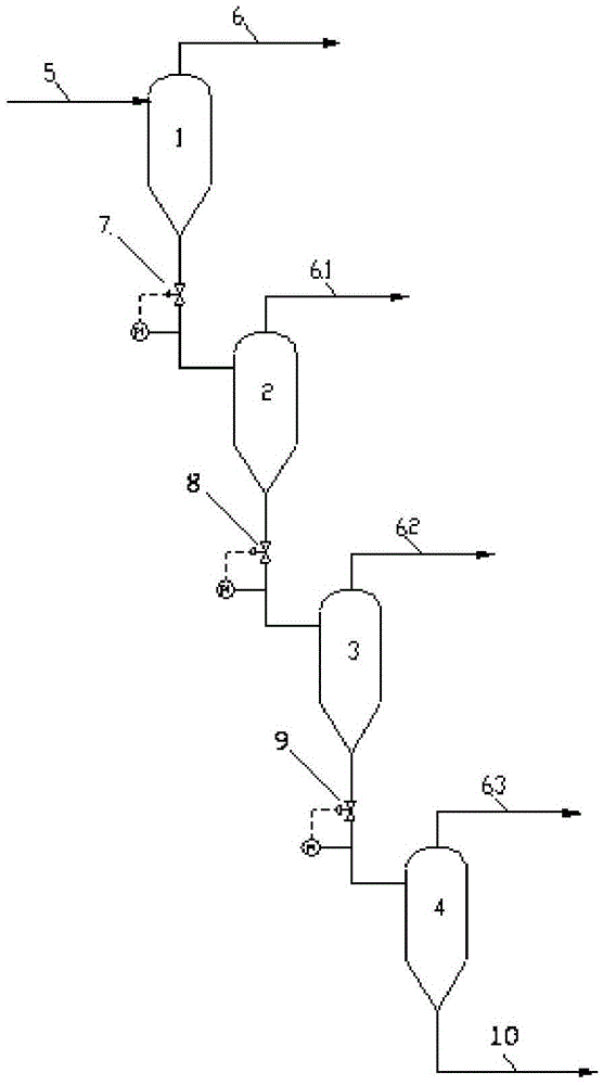
[0020] For further elaborating specific features of the present invention, will combine figure 1 To illustrate.

[0021] This example introduces the decompression separation method for separating gas, liquid and solid three-phase fluids in the separation system of the oil-coal co-refining slurry bed hydrogenation process. Its main purpose is to reduce the three-phase mixed fluid from high pressure to low pressure, so as to Light components are separated in the form of gas phase during the depressurization process. This example only introduces the high temperature and decompression series in the separation system.

[0022] The specific method is to set up four separate buffer tanks connected in sequence, and set a first-stage pressure reducing valve 7, a second-stage pressure-reducing valve 8, and a third-stage pressure-reducing valve 9 on the pipeline between adjacent buffer tanks to realize step-by-step Buck. Set the pressure-taking point after the pressure-reducing valve o...


PUM


Abstract

The invention provides a step-by-step pressure reduction method of three-phase fluid as well as a design method and an application thereof. The three-phase fluid flows through at least pressure-reducing valves of two stages for completing pressure reduction, in order to separate light components; the pressure of the three-phase fluid before a first pressure reduction is equal to or higher than 15MPa, and the pressure of the three-phase fluid after the last pressure reduction is equal to or lower than 5MPa; contents of gas phase, liquid phase and solid phase in the three-phase fluid are equal to or high than 1wt%. The pressure drop range of each stage is reduced by the step-by-step pressure reduction method, so that degrees of expansion type wearing and cavitation type wearing of equipment and valves are directly and greatly reduced; especially the reasonable pressure reduction range is optimally and further designed, so that medium flows more stably when the pressure drop range is reduced, wearing brought by solid-phase friction is greatly reduced, service life of pressure-reducing valves is prolonged, and possibilities of apparatus shutdown and accident appearance are reduced.

Description

technical field [0001] The invention relates to a step-by-step decompression method for a three-phase fluid, its design method and application, and belongs to the fields of petrochemical and coal chemical industries. Background technique [0002] In recent years, with the continuous increase of crude oil production and the continuous decrease of conventional crude oil reserves, the trend of inferior crude oil has become more and more serious. Oil refiners have focused on the secondary processing of heavy oil in order to obtain higher light oil yields. However, traditional processes such as delayed coking, catalytic cracking, and solvent deasphalting have been criticized for their serious pollution. Therefore, relatively environmentally friendly hydrogenation processes such as heavy oil hydrogenation, oil-coal co-refining, and direct coal liquefaction have emerged. [0003] The above three hydrogenation processes will produce coke when the hydrogenation is not timely, so ther...

Claims


Application Information

Patent Timeline
IPC IPC(8): C10G31/00C10G67/02C10G1/00
CPCC10G1/00C10G31/00C10G67/02C10G1/002C10G2300/1037C10G2300/107C10G2300/1077
Inventor 李苏安邓清宇王靖宇
Owner CATECH TECH
Learn More