Segmented blades, method of connecting segmented blades and wind turbine generating unit

A blade and segment technology, applied in the field of wind turbines, can solve the problems of low reliability, increased blade weight, low performance of structural adhesive, etc., and achieves the effect of high connection reliability and reduced fatigue load.

Active Publication Date: 2018-05-29
JIANGSU GOLDWIND SCI & TECH CO LTD
View PDF11 Cites 11 Cited by
  • Summary
  • Abstract
  • Description
  • Claims
  • Application Information

AI Technical Summary

Problems solved by technology

For the bolted connection, it is necessary to increase the thickness of the FRP at the position of the bolted connection, and at the same time increase the bolts and nuts and other devices, which will lead to an increase in the weight of the blade; in addition, with the operation of the wind turbine, the pre-tightening force of the bolts gradually decreases. The preload on the bolt becomes the main problem
For the connection method of structural adhesive, the performance of structural adhesive itself is relatively low, it can only bear shear stress, and cannot bear excessive load, and its reliability is relatively low

Method used


Image

  • Segmented blades, method of connecting segmented blades and wind turbine generating unit
  • Segmented blades, method of connecting segmented blades and wind turbine generating unit
  • Segmented blades, method of connecting segmented blades and wind turbine generating unit

Examples


Embodiment Construction

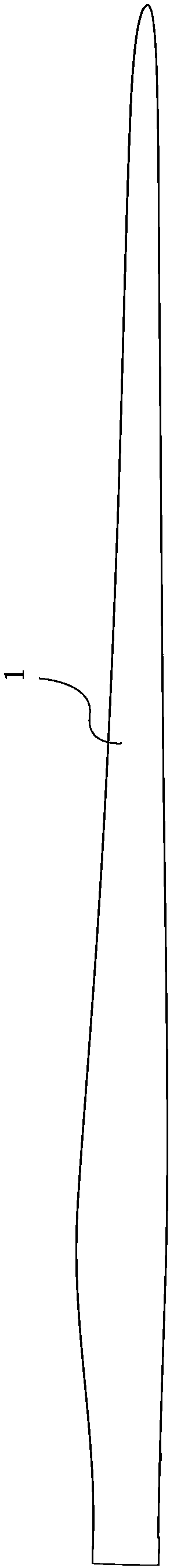
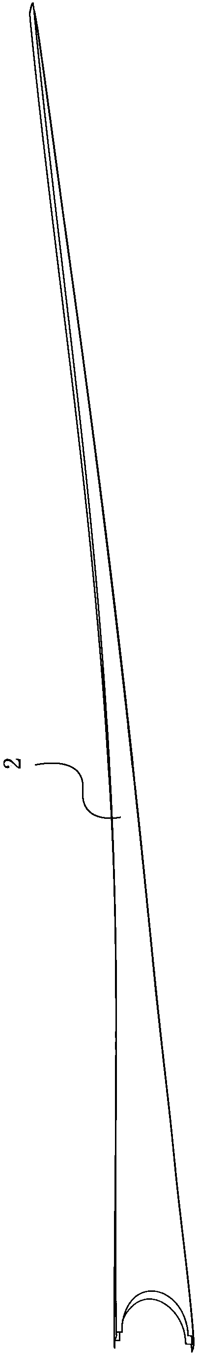
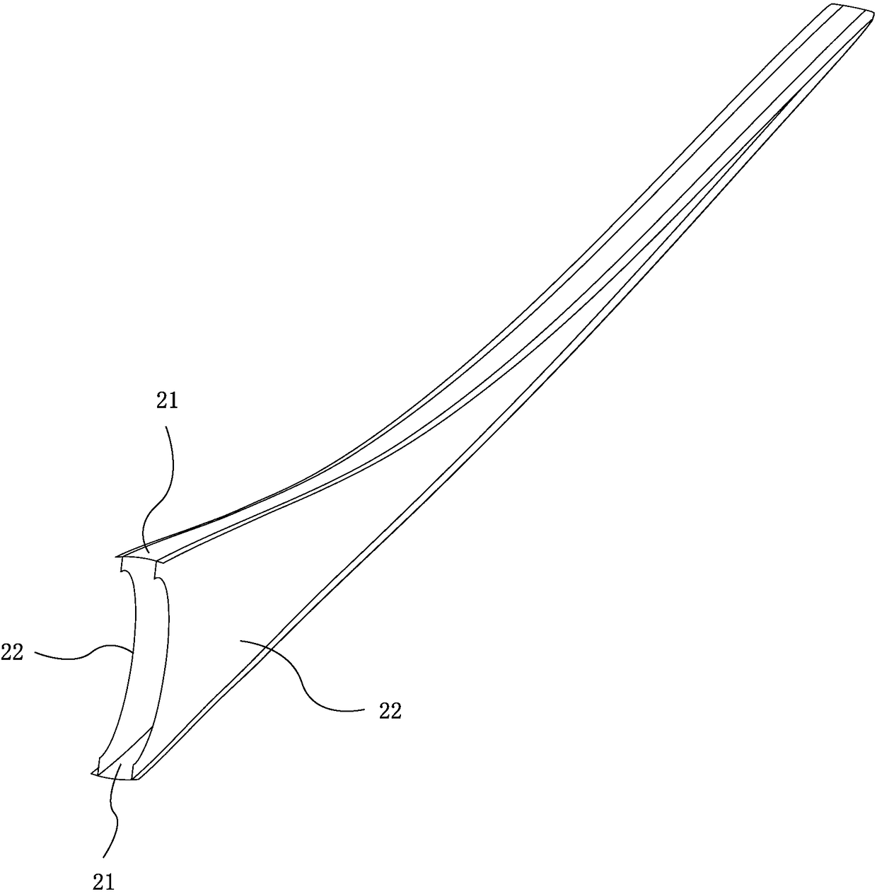
[0037] First, refer to Figure 1 to Figure 3 Describe the shape of a conventional blade. in, figure 1 is a schematic diagram of the shape of a conventional blade, figure 2 is the schematic diagram of the main beam of the blade, image 3 Yes Yes figure 2 Schematic illustration of the blade in the other direction of the main beam.

[0038] Wind turbines can include such figure 1 Blade 1 shown, as figure 1 As shown, the blade 1 becomes thinner from the root to the tip. figure 2 with image 3 The main spar 2 in can be arranged in the blade 1 . The spar 2 may comprise two spar caps 21 and two shear webs 22 . One of the two spar caps 21 may be arranged on the upper shell of the blade 1 and the other of the two spar caps 21 may be arranged on the lower shell of the blade 1 . Two shear webs 22 are used to support the two spar caps 21 on both sides of the two spar caps 21 . Such as image 3As shown, the height of the shear web 22 is getting smaller and smaller, that is, ...


PUM


Abstract

The invention provides segmented blades, a method of connecting the segmented blades and a wind turbine generating unit. The segmented blades comprise a first blade section provided with a first mainbeam, a second blade section provided with a second main beam and outer skin, wherein the first blade section is close to the blade root side and the first main beam comprises a first main body portion arranged in the first blade section and a first locking portion extending toward a direction, far from a blade root, from the end portion of the first main body portion, and the height of the firstlocking portion is gradually reduced along the direction far from the blade root; the second blade section is close to the blade tip side, the second main beam comprises a second main body portion arranged in the second blade section and a second locking portion extending toward a direction, close to the blade root, from the end portion of the second main body portion, and the height of the secondlocking portion is gradually increased along the direction close to the blade root; the second locking portion is locked into the first locking portion; and the outer skin wraps a gap between the first blade section and the second blade section. According to the segmented blades provided by the invention, the weights of the blades are not increased substantially, and the blades are connected withhigh reliability.

Description

technical field [0001] The present invention relates to the technical field of wind power generating sets, and more specifically, the invention relates to a segmented blade, a method for connecting segmented blades and a wind generating set. Background technique [0002] Wind turbines are used to convert wind energy into electrical energy. At present, with the increase of the megawatt level of the wind power generating set, the blades gradually become longer. For the manufacture and transportation of the blades, the gradually longer blades become a prominent problem restricting the development of wind power. [0003] In order to solve the above-mentioned problems, the blade can be manufactured in sections and the segmented blades can be assembled into a complete blade when used. At present, bolt connection or structural glue connection is usually used. For the bolted connection, it is necessary to increase the thickness of the FRP at the position of the bolted connection, ...

Claims


Application Information

Patent Timeline
Patent Type & Authority Applications(China)
IPC IPC(8): F03D1/06
CPCF03D1/0675Y02E10/72F05B2240/302F05B2250/292F05B2240/301F05B2260/30F05B2280/6003
Inventor 王兴波朱雨郝刘峰
Owner JIANGSU GOLDWIND SCI & TECH CO LTD
Why Eureka
Try Eureka