
Interferometric Phase Filtering Method Based on Difference Map and Compensation Filtering

A technology of interferometric phase and interferometric phase diagram, which is applied in the intersecting field of remote sensing and signal processing, can solve the problems of not giving the calculation method of filtering input parameters, destroying the continuity of interference fringes, etc., and achieve the effect of reducing density and ensuring continuity

Active Publication Date: 2018-11-09
湖南鼎方量子科技有限公司
View PDF7 Cites 0 Cited by
  • Summary
  • Abstract
  • Description
  • Claims
  • Application Information

AI Technical Summary

Problems solved by technology

[0004] However, there are two problems in applying BM3D filtering algorithm to interferometric phase filtering: (1) For dense interference fringes, since the filtering window of BM3D filtering algorithm may span multiple interference fringes, the continuity of interference fringes will be destroyed; (2) The BM3D filtering algorithm needs adaptive parameters that can represent the variance of the image noise as the filtering input parameters. Different filtering input parameters will lead to different filtering results, but the existing BM3D filtering algorithm does not provide a calculation method for the filtering input parameters.

Method used


Image

  • Interferometric Phase Filtering Method Based on Difference Map and Compensation Filtering
  • Interferometric Phase Filtering Method Based on Difference Map and Compensation Filtering
  • Interferometric Phase Filtering Method Based on Difference Map and Compensation Filtering

Examples


Embodiment Construction

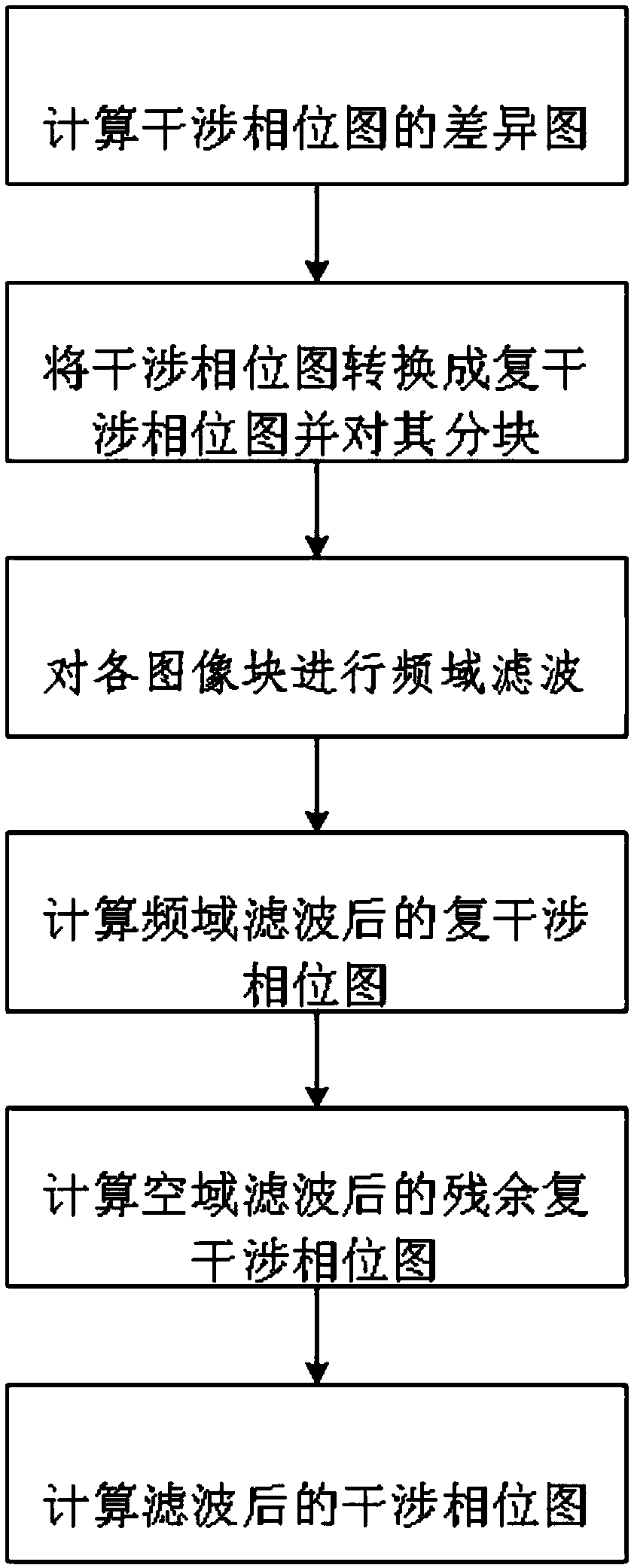
[0101] refer to figure 1 , is a flowchart of the interferometric phase filtering method based on the difference map and compensation filtering of the present invention, comprising the following steps:

[0102] S1. Calculate the difference map of the interferometric phase map;

[0103] Suppose the size of the interferogram to be filtered (that is, the input interferogram) is N x ×N y Pixel, the pixel value ([-π,π]) of the interferometric phase image pixel is quantized into 13 values, and the quantization adopts For the uniform quantization of the interval, the quantized pixel value set G is obtained. Finally, a new mapping relationship is obtained: f:X×Y→G, where X={1,2,3,…,N x}, Y={1,2,3,...,N y}, The difference map DM(G i ,G j) is calculated as:

[0104]

[0105] Among them, i is any pixel point in the interferometric phase map, j is any pixel point among the 8 pixel points centered on pixel point i and adjacent to pixel point i, G i is the quantized pixel valu...


PUM


Abstract

The invention provides an interferometric phase filtering method based on a difference chart and compensation filtering. The interferometric phase filtering method comprises the steps of: firstly, extracting principal components of interferometric phases from an input interferometric phase image through frequency domain filtering based on the differential chart, so as to reduce density of interferometric fringes in the residual interferometric phase image and facilitate subsequent processing; and secondly, performing compensation filtering on the residual interferometric phase image, wherein compensation filtering adopts BM3D filtering taking a phase derivative variogram of the residual interferometric phase image as self-adaptive filtering parameters, and can better extract detail components of the interferometric phases. The interferometric phase filtering method comprises frequency domain filtering and space domain filtering, is suitable for processing the interferometric phases containing dense interferometric fringes, and can effectively filter out noise without destroying the continuity of the dense interference fringes.

Description

technical field [0001] The invention belongs to the intersecting technical field of remote sensing and signal processing, in particular to an interference phase filtering method suitable for dense interference fringes. Background technique [0002] The interferometric phase is obtained by conjugate multiplication of two SAR images and taking the phase of the multiplication result. Interferometric phase is an important physical quantity in SAR interferometry, and its quality will determine the accuracy of the final product—digital elevation model or terrain deformation. However, due to decorrelation factors, there is always serious space-varying noise in the interferometric phase. Space-variant noise will not only introduce residual points but also destroy the distribution of the interferometric phase, which increases the difficulty of subsequent phase unwrapping and eventually leads to a decrease in product accuracy, so it must be filtered out through the interferometric ph...

Claims


Application Information

Patent Timeline
Patent Type & Authority Patents(China)
IPC IPC(8): G06T5/00G06T5/10G06F17/14
CPCG06F17/141G06T5/002G06T5/10G06T2207/20021
Inventor 申倍铭周建元
Owner 湖南鼎方量子科技有限公司
Learn More