Cabinet for electronic communication

A chassis and communication technology, applied in the direction of chassis/cabinet/drawer parts, electrical equipment shell/cabinet/drawer, electrical components, etc., can solve the problem of increasing product cost maintenance, shortening the service life of electronic communication equipment, electronic communication Problems such as shortening the service life of the chip

Active Publication Date: 2018-05-29
HARBIN UNIV
View PDF6 Cites 0 Cited by
  • Summary
  • Abstract
  • Description
  • Claims
  • Application Information

AI Technical Summary

Problems solved by technology

The box installed with electronic communication components has the following problems during use: First, electronic communication equipment basically needs to be used continuously for a long period of time, so it will generate a lot of heat during work. , the heat is accumulated, and there is no effective heat dissipation channel between the traditional boxes, which leads to an increase in the temperature of the box, shortens the service life of the electronic communication chip, and also affects its normal working state
The second is that the traditional electronic communication is installed in the box. Due to long-term work, more dust, dust and other dust particles will be formed in the box, and the above-mentioned dust will be adsorbed on the electronic communication chip, thus affecting its normal operation. Work, causing communication interruption, also shortens the service life of electronic communication equipment, thereby increasing product costs and later maintenance

Method used


Image

  • Cabinet for electronic communication
  • Cabinet for electronic communication
  • Cabinet for electronic communication

Examples


Embodiment Construction

[0021] The present invention will be described in detail below in conjunction with the accompanying drawings and specific embodiments, wherein the schematic embodiments and descriptions are only used to explain the present invention, but are not intended to limit the present invention.

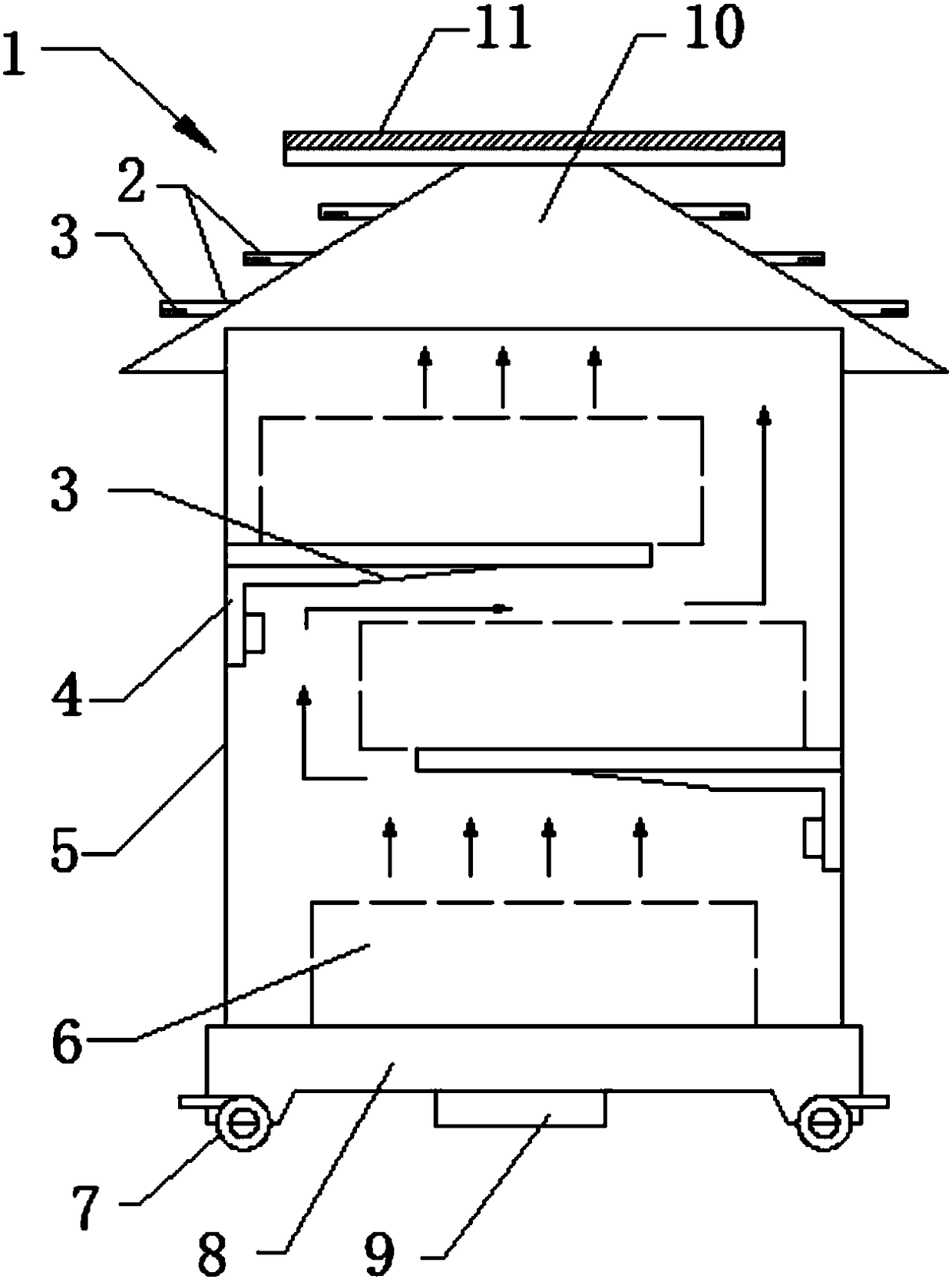
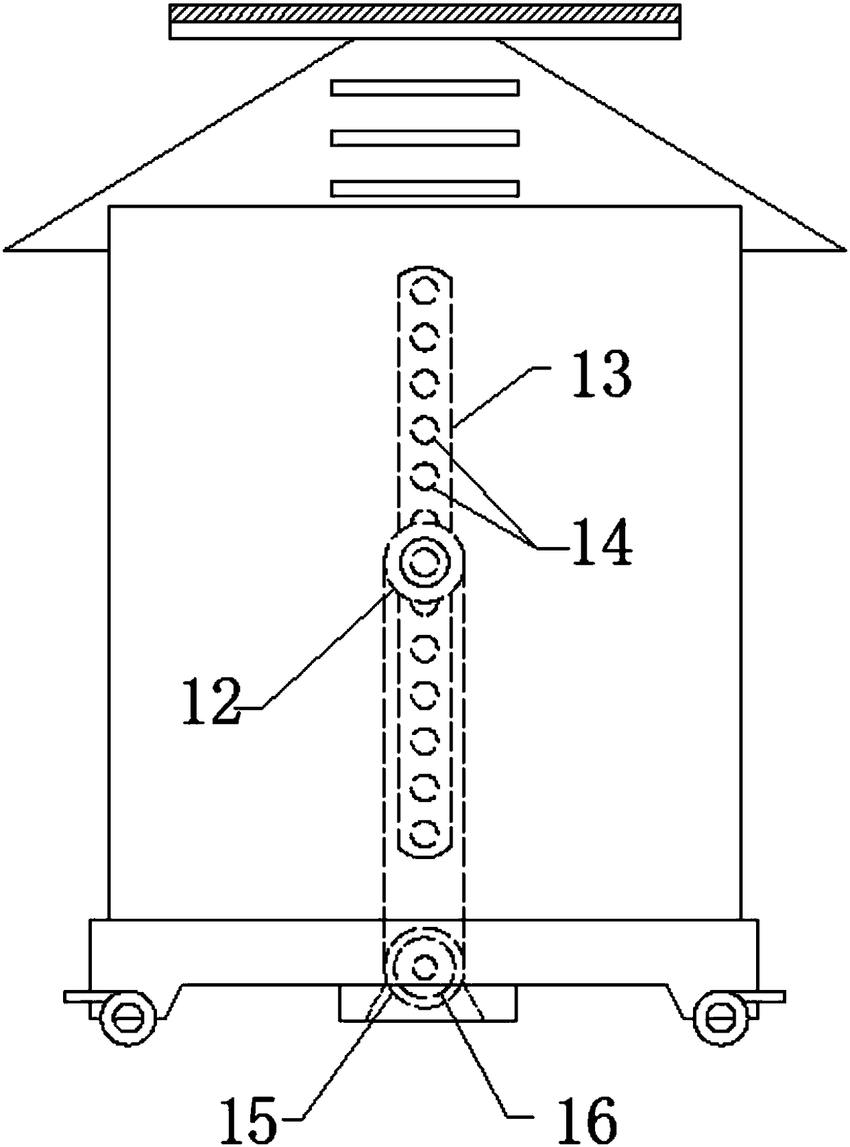
[0022] like Figure 1-Figure 3 As shown, a case for electronic communication described in this specific embodiment includes a case body 1, the case body 1 includes a base 8, a groove is arranged in the middle of the bottom surface of the base 8, and a convex shell 9 is arranged on the groove, A motor 16 is installed in the convex shell 9;

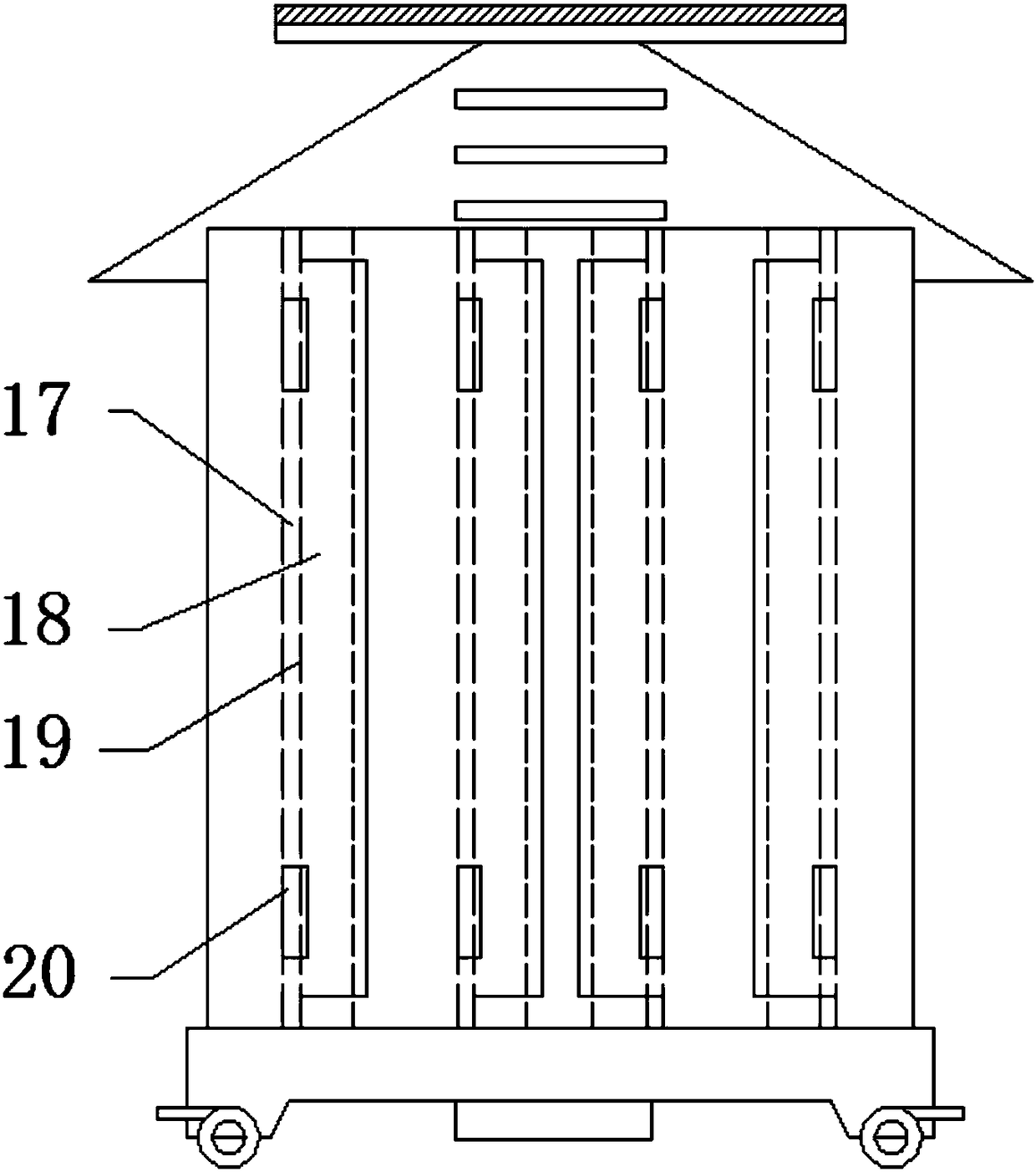
[0023] Described base 8 is provided with box body 5, and this box body 5 is cylindrical cylinder shape, and this box body 5 is provided with some inverted L-shaped brackets 4 on the left and right sides; A number of inverted L-shaped brackets 4 and a number of inverted L-shaped brackets 4 on the right side wall of the box body 5 are arranged in a dislocati...


PUM


Abstract

The invention belongs to the electronic communication auxiliary tool technical field and relates to a cabinet for electronic communication. The cabinet comprises a cabinet body; the cabinet body comprises a base; a groove is formed in the bottom surface of the base; a protruding shell is arranged in the groove; a motor is mounted inside the protruding shell; a box body is arranged on the base; thebox body is in the shape of a cylinder; a plurality of inverted-L-shaped supporting brackets are arranged at a left side and a right side inside the box body; the plurality of inverted-L-shaped supporting brackets at the left side inside the box body and the plurality of inverted-L-shaped supporting brackets at the right side inside the box body are arranged in a staggered manner; and the inverted-L-shaped supporting brackets are fixed onto the inner walls of the left side and right side inside the box body through screws. According to the cabinet for electronic communication of the invention, a conical heat dissipation box top cover, the clamping supporting brackets which are distributed in different layers in a staggered manner and a dust removal component are adopted. The cabinet for electronic communication has the advantages of convenient use and high efficiency. With the cabinet for electronic communication adopted, heat dissipation and dust removal can be facilitated; the normal use of electronic communication equipment can be ensured; the service life of the electronic communications equipment can be prolonged; maintenance at later stages can be decreased; and product comprehensive costs are reduced.

Description

【Technical field】 [0001] The invention relates to the technical field of electronic communication auxiliary appliances, in particular to a case for electronic communication. 【Background technique】 [0002] With the development of science and technology, the current society has entered the era of electronic communication. The emergence of the Internet has made electronic communication step into a stage of rapid development. The nodes and terminals of the Internet need electronic communication equipment as support. The box installed with electronic communication components has the following problems during use: First, electronic communication equipment basically needs to be used continuously for a long period of time, so it will generate a lot of heat during work. , the heat is accumulated, and there is no effective heat dissipation channel between the traditional cabinets, resulting in an increase in the temperature of the cabinet, shortening the service life of the electro...

Claims


Application Information

Patent Timeline
IPC IPC(8): H05K5/02H05K7/20H05K7/14B08B5/02B08B13/00
CPCB08B5/02B08B13/00H05K5/0213H05K5/0217H05K7/14H05K7/20136
Inventor 曲明哲赵莹
Owner HARBIN UNIV
Why Eureka
Try Eureka