Agricultural rotary cultivator

A rotary tiller, agricultural technology, applied in agriculture, agricultural machinery and implements, animal husbandry, etc., can solve the problems of low tillage efficiency, fuel consumption, time, poor effect, etc., and achieve the effect of improving efficiency and effect

Inactive Publication Date: 2018-06-01
NANJING ZHIQIAO AGRI CO LTD
0 Cites 0 Cited by

AI-Extracted Technical Summary

Problems solved by technology

This kind of farming machine has the following disadvantages: first, the soil is easy to adhere to the rotary digging knife or the soil breaking knife, which requires manual cleaning, which is time-consuming and laborious. If it is not cleaned, the farming machine will be dragged down, which consumes fuel and time; The soil efficiency is not high, and the effect is not good. In order to obtain crushed soil with a certain particle size, it is usually necessa...

Abstract

The invention discloses an agricultural rotary cultivator. The agricultural rotary cultivator comprises a frame, a rotary excavating device, a soil scattering device, a gas-liquid supply and a drivingdevice; the frame is provided with a vertical beam and multiple cross beams which are crossed to form four included angles, a circular shaft is arranged at the junction so as to make the vertical beam and the cross beams rotate relatively, the first included angle and the third included angle are each internally provided with a telescopic part, and the two ends of the telescopic part are connected to the vertical beam and the cross beams respectively to conduct telescopic adjustment on the included angles; the second included angle and the fourth included angle are each internally provided with an elastic part, and the two ends of the elastic part are connected to the vertical beam and the cross beams respectively so as to elastically pull or support the vertical beam and the cross beams;any one end of the vertical beam is detachably provided with a hook connected with a trailer; the rotary excavating device is hung on the cross beams; the soil scattering device is hung on the crossbeams and located behind the rotary excavating device, the soil scattering device comprises an air cannon, one end of the air cannon is fixed to the cross beam, and the other end extends downwards toblow apart soil; the gas-liquid supply device is arranged on the upper portion of the frame; the driving device is arranged on the frame.

Application Domain

SpadesWatering devices +3

Technology Topic

Agricultural engineeringAgriculture

Image

  • Agricultural rotary cultivator
  • Agricultural rotary cultivator
  • Agricultural rotary cultivator

Examples

  • Experimental program(1)

Example Embodiment

[0028] The present invention will be further described in detail below with reference to the accompanying drawings, so that those skilled in the art can implement it with reference to the text of the description.
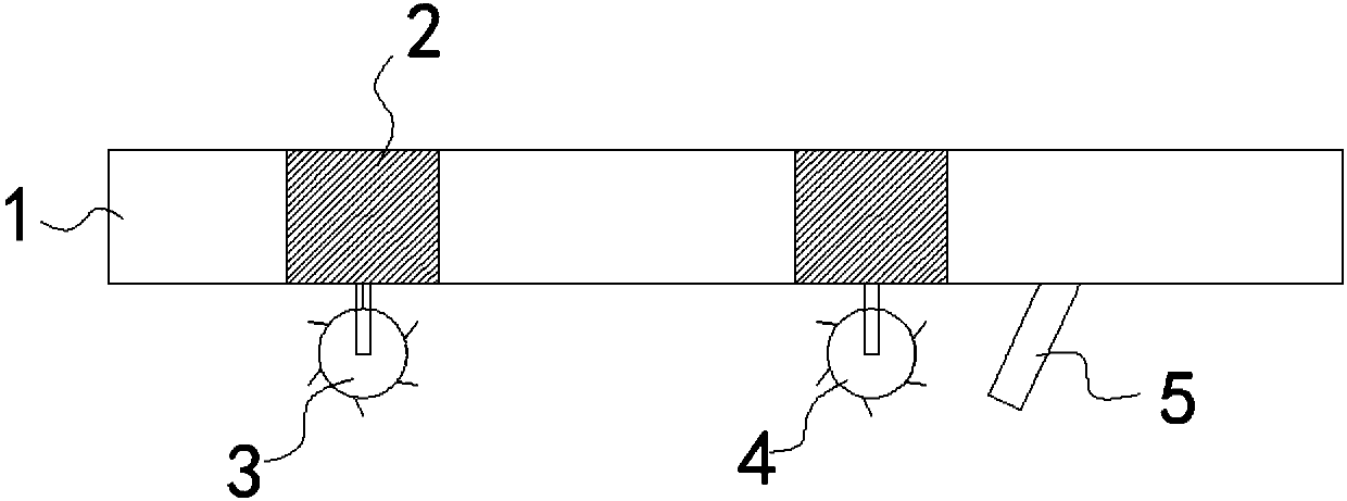
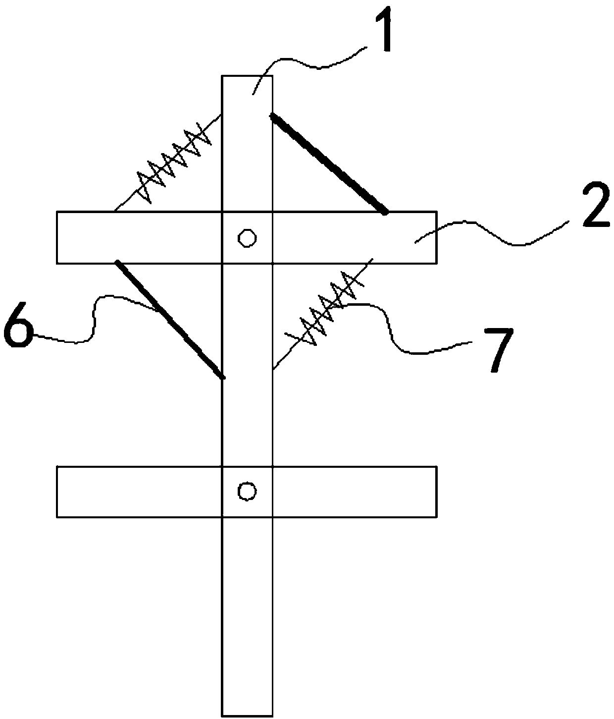
[0029] Such as figure 1 , 2 , 3 and 4, an agricultural rotary cultivator, which includes:
[0030] The frame is provided with a vertical beam 1 and a plurality of cross beams 2, the vertical beam and the cross beam cross to form a first, second, third and fourth included angle, the first and third included angles are opposite, and the second It is opposite to the fourth included angle, and a circular shaft is provided at the intersection to allow the vertical beam and the cross beam to rotate relative to each other. Bearings can also be provided at the intersection, and the circular shaft is sleeved in the bearing to realize the cross beam to rotate relative to the vertical beam . Telescopic members 6 are respectively arranged in the first and third included angles, and two ends of the telescopic members 6 are respectively connected to the vertical beam 1 and the cross beam 2 to adjust the included angle by telescoping, and the cross beam can be pulled when the telescopic member is telescopic Relative to the vertical beam deflection, an elastic member 7 is arranged in the second and fourth included angles, and two ends of the elastic member are respectively connected to the vertical beam and the cross beam to elastically pull or support the vertical beam and the cross beam. Any end of the vertical beam 1 is detachably provided with a hook for connecting with a trailer. In this way, the cross beam 2 and the vertical beam 1 are in tension, which increases the stability of the structure. The vertical beam is arranged along the length of the frame, and the cross beam is arranged along the width of the frame. The telescopic part can adjust the angle between the cross beam and the vertical beam. When the angle becomes smaller, the width covered by the cross beam becomes smaller. figure 2 Shown.
[0031] Rotary digging device 3, which is hung on the cross beam 2. The rotary digging device includes a first rotating shaft and a rotary cutter arranged on the first rotating shaft. The first rotating shaft is arranged along the length direction of the cross beam , The first rotating shaft is of a hollow structure, and a first pipe for passing water or gas is arranged inside, a plurality of spray holes are evenly arranged on the knife surface of the rotary cutter, and the rotary cutter can also be hollow Structure, so that the first pipe can be connected to the spray hole through the inside of the rotary knife; high-pressure water or gas is sprayed from the nozzle hole on the rotary knife face after passing through the first pipe, which can prevent sticking The soil attached to the knife surface is sprayed down, and on the one hand, the airflow forms a protective layer on the knife surface to prevent the soil from sticking again.
[0032] A loose soil device 4, which is suspended on the beam 2 and located behind the rotary digging device 3. The loose soil device 4 includes: a second rotating shaft, a crushing knife arranged on the second rotating shaft, and The air cannon 5 is located behind the second rotating shaft. The second rotating shaft is arranged along the length of the beam. One end of the air cannon is fixed on the beam 2 and the other end extends downward until the soil generates air. The air cannon 5 should not be deeper than the depth of the rotary digging knife or the earth-breaking knife, so as to avoid the air cannon 5 directly inserted into the deep hard soil and be damaged.
[0033] The gas-liquid supply device is arranged above the frame, and the gas-liquid supply device is respectively communicated with the first pipe and the air cannon, and is used to provide liquid to the first pipe and the air cannon 5 or Gas; on the one hand, the gas-liquid supply device can provide gas for the air cannon 5 to ensure that the air cannon 5 can operate normally, on the other hand, some pesticides, fertilizers or moisture can be supplied to the air cannon through the gas-liquid supply device, so that the pesticide, Fertilizer or water can be exploded into the soil to achieve the purpose of spraying, fertilizing and irrigation. The gas-liquid supply device can be a conventional device. Generally speaking, the gas-liquid supply device is equipped with an air pump. The air pump is connected to a venturi tube to pump gas into the venturi tube, and a water tank is also provided, and the water tank is connected to the venturi tube through the water tube. The water pipe is provided with a water valve to control whether water is introduced, so that the air pump can provide gas or a gas-liquid mixture to the first pipe or the air cannon 5, and the water tank can be filled with liquid pesticides, liquid fertilizers or water.
[0034] The driving device is arranged on the frame to drive the frame to travel and to drive the first rotating shaft and the second rotating shaft to rotate. The driving device includes a power mechanism and a transmission mechanism. The power is transmitted from the power mechanism to the wheels of the frame through the transmission mechanism to drive forward, and is also transmitted to the first and second transmission shafts to drive the rotation shaft to rotate.
[0035] Further, such as image 3 As shown, the air cannon includes: a cylinder 8 whose one end is closed and the other end is open, and the cylinder has a compression chamber 9 inside; and a piston, which fits from the open end of the cylinder 8 to the compression chamber 9 The power mechanism 11 drives the piston to move back and forth along the compression chamber 9 to continuously produce high-pressure gas, that is, continuously inhale and compress the gas. The power mechanism can be a motor with a crankshaft mechanism. The rotation is converted into linear motion, thereby pushing the reciprocating motion of the piston. Wherein, the closed end of the cylinder 8 is provided with a spout 12, and the spout 12 can be provided with a constant pressure valve to prevent the gas from freely overflowing. A gas-liquid inlet 13 is provided on the side wall of the cylinder to communicate with the compression chamber 9, and a one-way valve is provided on the gas-liquid inlet 13 to allow gas and liquid to flow into the compression chamber 9 in one direction. The back and forth movement of the piston causes the compression chamber to inhale and deflate. The gas or liquid enters from the gas-liquid inlet 13 and is compressed to form a certain high-pressure gas-liquid and then ejected from the nozzle 12. As the jet is completed in an instant, a strong gas is produced Explode, thereby blowing up or loosening the soil.
[0036] Further, the air cannon further includes a control module, the control module includes a controller, a solenoid valve arranged on the nozzle 12, and a pressure sensor for detecting the air pressure inside the compression chamber, the solenoid valve and the pressure sensor are both The controller is electrically connected; the controller is configured to: preset a pressure limit; receive a pressure signal from a pressure sensor; when the received pressure is greater than or equal to the pressure limit, control the solenoid valve Open the spout; when the received pressure is less than the pressure limit, control the solenoid valve to close the spout. The pressure limit can be set artificially in advance. When the soil is too hard, the pressure limit can be appropriately increased. When the soil is soft, the pressure limit can be appropriately lowered. The pressure limit ensures that the gas or liquid is ejected at a certain pressure to ensure an explosion Effect.
[0037] Further, such as Figure 4 As shown, an arc-shaped or semi-circular cover 15 is provided above the rotary digging device and the loose soil device, and the cover plays a role of collecting dust. The top of the cover is provided with suction holes, and the suction holes It is connected to a storage tank 17 through the second pipe 16, and a pressure pump is arranged in the storage tank 17. When the pressure pump pumps air, dust is sucked in from the suction hole, passes through the second pipe 16, and finally enters the storage tank 17, Therefore, the effect of sucking the dust generated by the rotary digging device and the soil scattering device into the storage tank 17 is achieved. The dust generated by the rotary digging device and the loose soil device rises, is stored in the cover, and then sucked away by the suction hole. The dust enters the storage tank through the suction hole, thereby achieving the effect of dust removal.
[0038] Further, the gas-liquid inlet 13 is in communication with the storage tank 17. After the dust is sucked into the storage tank, it is sucked away by the air cannon, and then sprayed into the depths of the mud again. The dust is trapped by the mud and returned to the mud, killing two birds with one stone.
[0039] Further, the closed end of the cylinder 8 is also sleeved with a cone-shaped cap body 14, the cone tip of the cone-shaped cap body is provided with an opening to communicate with the spout 12, and the cylinder is inclined downward and forward. The forward tilt of the cylinder can be better inserted into the soil, and the cone-shaped cap can reduce the resistance of the soil.
[0040] Further, the frame is provided with at least two wheels. Conducive to mobile.
[0041] Further, the telescopic member is an electric telescopic member, and an electric switch is provided on the frame, and the electric switch is connected in series with the electric telescopic member, and the electric switch is controlled to drive the electric telescopic member to change the cross beam and the vertical beam The angle of intersection. The electric switch can be set in the cab to facilitate the driver to adjust the width of the beam. When it is necessary to deal with small-row planting land or when passing through a narrow passage, control the electric switch to make the electric telescopic member expand and contract, and the electric telescopic member pulls or pushes the cross beam to tilt relative to the vertical beam, thereby narrowing the frame as a whole, thereby enabling Planting land in small rows, or through narrow passages.
[0042] Although the embodiments of the present invention have been disclosed as above, they are not limited to the applications listed in the specification and embodiments. It can be applied to various fields suitable for the present invention. For those skilled in the art, additional modifications can be easily implemented. Therefore, without departing from the general concept defined by the claims and equivalent scope, the present invention is not limited to the specific details and the illustrations shown and described herein.

PUM

no PUM

Description & Claims & Application Information

We can also present the details of the Description, Claims and Application information to help users get a comprehensive understanding of the technical details of the patent, such as background art, summary of invention, brief description of drawings, description of embodiments, and other original content. On the other hand, users can also determine the specific scope of protection of the technology through the list of claims; as well as understand the changes in the life cycle of the technology with the presentation of the patent timeline. Login to view more.

Similar technology patents

Beauty makeup processing method and device, terminal and storage medium

PendingCN111783511AReal makeup experienceImprove efficiency and effectiveness
Owner:BEIJING WODONG TIANJUN INFORMATION TECH CO LTD +1

Plasma disinfection and sterilization device for medical instruments

PendingCN111202857AGood disinfection and sterilization effectImprove efficiency and effectiveness
Owner:UNIV OF SCI & TECH OF CHINA

Lake exogenous sewage purification system

PendingCN112093900AEfficient collection and purificationImprove efficiency and effectiveness
Owner:中国冶金科工股份有限公司 +1

Classification and recommendation of technical efficacy words

Why Eureka
Try Eureka