High-pressure heating tank and machining method of tank body of heating tank

A technology of high-pressure heating and processing methods, which is applied in the direction of tank cars, railway car body parts, transport passenger cars, etc., can solve the problems of energy waste, poor explosion-proof performance, and low energy utilization rate, and achieve the effect of improving efficiency and effect and ensuring safety

Inactive Publication Date: 2016-08-03
浙江宝峰热电有限公司
View PDF10 Cites 5 Cited by
  • Summary
  • Abstract
  • Description
  • Claims
  • Application Information

AI Technical Summary

Problems solved by technology

[0004] The shell of the heater disclosed in the above-mentioned patent document adopts a common structure, which is relatively simple, and its electric heating efficiency is not high, and the energy utilization rate is not high, resulting in serious waste of energy. In addition, the above-mentioned patent document

Method used


Image

  • High-pressure heating tank and machining method of tank body of heating tank

Examples


Example Embodiment

[0028] Embodiment one

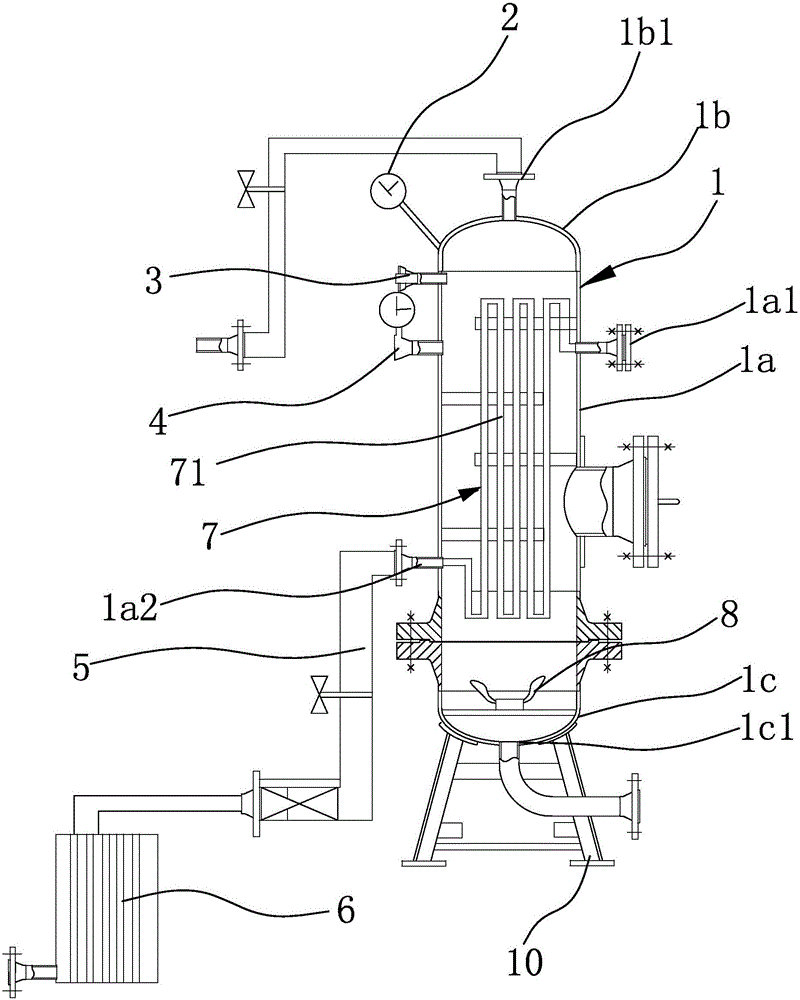
[0029] The high-pressure heating tank in this embodiment exchanges heat with the liquid through hot steam to achieve the purpose of heating the liquid; as figure 1 As shown, the high-pressure heating tank includes a base 10 and a tank body 1 fixed on the base 10. The tank body 1 is respectively provided with a barometer 2, a pressure relief valve 3 and a thermometer 4; the tank body 1 includes a long cylindrical tube body 1a, upper end cover 1b and upper end cover 1c, the cylinder body 1a is vertically arranged and the upper end cover 1b and the upper end cover 1c are fixedly connected to the upper and lower ends of the cylinder body 1a respectively and can seal both ends of the cylinder body 1a; There is a liquid inlet 1b1, and a liquid outlet 1c1 is opened on the upper end cover 1c; a heat exchange channel 7 is provided in the tank body 1, and an air inlet 1a1 and an air outlet that communicate with the heat exchange channel 7 are respectively opened ...

Example Embodiment

[0032] Embodiment two

[0033] A processing method for a high-pressure heating tank body is provided in this embodiment, and the processing method includes the following steps:

[0034] a: Prepare cylinder 1a: use stainless steel material to go through continuous casting slab heating → rough descaling → constant width press → rough rolling → coil box → flying shear → fine descaling → finish rolling → laminar cooling → coiling Form a cylinder 1a; both ends of the cylinder 1a are rolled and pressed with a flange 1, and the air inlet 1a1 and the air outlet 1a2 are punched out on the side of the cylinder 1a; the laminar flow cooling method adopts the front-end rapid cold rolling and the rear section The combination of precise cooling; the coiling temperature is 600°C.

[0035] b: Prepare upper end cap 1b and upper end cap 1c: produce upper end cap 1b and upper end cap 1c matching the above-mentioned cylinder 1a through powder metallurgy process; the periphery of upper end cap 1b ...


PUM


Abstract

The invention provides a high-pressure heating tank and a machining method of a tank body of the heating tank, and belongs to the technical field of heating devices. The technical problems that an existing heating device is low in efficiency and utilization rate and the like are solved. The high-pressure heating tank comprises a base and the tank body fixedly arranged on the base; a gas-pressure meter, a pressure relief valve and a thermometer are arranged on the tank body; the tank body comprises a long-cylinder-shaped cylinder body, an upper end cover and a lower end cover; the cylinder body is vertically arranged, the upper end cover is fixedly connected to the upper end of the cylinder body, the lower end cover is fixedly connected to the lower end of the cylinder body, and the two ends of the cylinder body can be sealed; a liquid inlet is formed in the upper end cover, and a liquid outlet is formed in the lower end cover; a heat exchange channel is formed in the tank body, a gas inlet and a gas outlet which are communicated with the heat exchange channel are formed in the cylinder body, and a stirrer facing the heat exchange channel is further formed in the lower end cover; and a condensation pipeline is connected to the gas outlet, and a condenser is connected to the condensation pipeline. According to the heating tank, liquid and steam heat exchange efficiency and effects are improved.

Description

technical field [0001] The invention belongs to the technical field of heating devices, and relates to a high-pressure heating tank and a processing method for the tank body. Background technique [0002] The high-pressure heating tank is one of the most widely used high-pressure heating devices. It is usually composed of two parts: the shell and the piping system. The steam condensing section is set on the upper part of the inner cavity of the shell, the drain cooling section is set on the lower part, and the water supply is set on the top of the inlet and outlet pipes. Inlet and outlet for water supply. When the superheated steam enters the shell from the inlet, it can heat the feed water in the upper main coil, and after the steam condenses into water, it flows out of the body through the drain outlet; it has the advantages of low energy consumption, compact structure, small occupied area, and low material consumption. Advantages, and can strictly control the hydrophobic...

Claims


Application Information

Patent Timeline
IPC IPC(8): B65D88/74B65D90/32B65D90/48B65D90/00
CPCB65D88/744B65D90/00B65D90/32B65D90/48
Inventor 朱延庆杨春福
Owner 浙江宝峰热电有限公司
Why Eureka
Try Eureka