
Polishing device and polishing method of 3D glass board

A polishing device and glass plate technology, applied in grinding/polishing equipment, machine tools for surface polishing, abrasives, etc., can solve the problems of low yield, high cost, and high price of 3D glass plate products, and achieve curved surface profile. Accurate radian, good repeat positioning accuracy, convenient and quick debugging

Pending Publication Date: 2018-06-01
LENS TECH CHANGSHA
View PDF0 Cites 4 Cited by
  • Summary
  • Abstract
  • Description
  • Claims
  • Application Information

AI Technical Summary

Problems solved by technology

Because the special polishing equipment only has several fixed modes of polishing, the traditional polishing equipment and polishing modes can only move up and down, back and forth, left and right when polishing a 3D free-form glass plate. The polishing equipment cannot match the 3D free-form surface during the polishing process. 3D glass The high point and low point of the plate are subjected to different forces, and the cutting amount of polishing is also different. The high point of the D glass plate is close to the upper plate, so the pressure is slightly higher, while the low point is slightly farther away from the upper plate, so the pressure is slightly smaller.
And the radian of the free-form surface of the 3D glass plate is difficult to control during the polishing process
Such a solution makes the yield rate of qualified products not high when polishing 3D glass plates. In addition, the utilization efficiency of materials such as polishing fluid, grinding discs and brushes in this method is not high, and the cost of labor, water, electricity, etc. Expensive, resulting in expensive 3D glass sheet products produced by such polishing methods

Method used


Image

  • Polishing device and polishing method of 3D glass board

Examples


Embodiment Construction

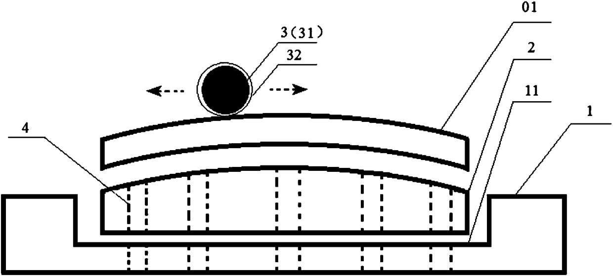
[0017] The invention provides a polishing device for a 3D glass plate. The 3D glass plate is a glass plate whose two ends in the length direction of the plate surface are bent toward the same direction. The polishing device includes a polymer base plate 1 (fiber plate), a curved rubber The plate 2 and the polishing rod 3 also include a vacuum suction channel 4 which is arranged on the polymer bottom plate 1 and the curved rubber plate 2 and is used for fixing the 3D glass plate during polishing. Plate 2 and cavity 11 positioned for the 3D glass plate, the curved rubber plate 2 includes a curved top surface and is used to support the 3D glass plate 01, the polishing rod includes a cylindrical steel core 31 and is fixedly arranged outside it The soft grinding skin 32 on the circular surface, the polishing rod 3 is arranged above the 3D glass plate 01 and the polishing rod is driven by external force to rotate so that the soft grinding skin of the polishing rod is in contact with ...


PUM

PropertyMeasurementUnit
thicknessaaaaaaaaaa
diameteraaaaaaaaaa
thicknessaaaaaaaaaa

Abstract

The invention provides a polishing device of a 3D glass board. The 3D glass board is a glass board with two ends in the length or with directions of a board surface bending towards the same direction.The polishing device comprises a high-molecular bottom board, a curved rubber board and a polishing rod. The device further comprises a vacuum air extraction passage used for fixing the 3D glass board during polishing. The high-molecular bottom board contains a cavity used for accommodating the curved rubber board and locating the 3D glass board. The curved rubber board comprises a bent top surface used for supporting the 3D glass board. The polishing rod comprises a cylinder steel core and soft grinding leather fixedly arranged on the external circular surface of the cylinder steel core. Thepolishing rod is arranged above the 3D glass board and drives the polishing rod to rotate through external force such that the soft grinding leather of the polishing rod contacts the 3D glass board in order to perform polishing operation. The polishing rod rotates while performing motion along the bending length direction or the width direction of the 3D glass board. The polishing yield rate of the 3D glass board is greatly increased so that polishing cost is greatly reduced.

Description

technical field [0001] The invention relates to the field of glass processing, in particular to a polishing device and a polishing method for a 3D glass plate. Background technique [0002] In the prior art, conventional glass polishing equipment includes upper and lower grinding discs rotating in opposite directions, which work together with diamond micropowder polishing liquid to polish the glass. During the polishing process, a brush is arranged on the upper grinding disc. In this way, the surface of the glass is flat ground and polished. Because the special polishing equipment only has several fixed modes of polishing, the traditional polishing equipment and polishing modes can only move up and down, back and forth, left and right when polishing a 3D free-form glass plate. The polishing equipment cannot match the 3D free-form surface during the polishing process. 3D glass The high point and low point of the plate are subjected to different forces, and the cutting amoun...

Claims


Application Information

Patent Timeline
Patent Type & Authority Applications(China)
IPC IPC(8): B24B29/02B24B41/06B24B1/00B24D9/04
CPCB24B1/00B24B29/02B24B41/06B24D9/04
Inventor 周群飞饶桥兵胡亮
Owner LENS TECH CHANGSHA
Learn More