Splicing type combination demolding mechanism for front grill mold of automobile

A technology of demolding mechanism and front grille, which is applied to household appliances, other household appliances, household components, etc., can solve the problem of difficulty in one-time processing of sliders, and achieve the advantages of convenient screw splicing, balanced pouring, and reduction of welding marks. Effect

Inactive Publication Date: 2018-06-01
余姚市宏硕模具制造有限公司
View PDF0 Cites 0 Cited by
  • Summary
  • Abstract
  • Description
  • Claims
  • Application Information

AI Technical Summary

Problems solved by technology

[0005] The splicing combined demoulding mechanism of the automobile front grille mold of the present invention is mainly characterized in that an outer slide block is arranged on one side of the movable template, an inner insert is spliced ​​on the inner wall of the outer slide block, and the inner insert and the inclined top insert The side mold cavity of the front grille is formed between the blocks, and the side mold cavity has the side of the front grille. Compared with the traditional large slider, after the large slider is divided into inner and outer parts, it can be divided into two parts. Select two kinds of mold materials with different quality to process and then splicing, which solves the problem of difficult one-time processing due to the large slider, and effectively improves the processing accuracy; moreover, the inner insert in the part in contact with the product can use better The mold material can greatly improve the service life of the mold and save costs

Method used


Image

  • Splicing type combination demolding mechanism for front grill mold of automobile
  • Splicing type combination demolding mechanism for front grill mold of automobile

Examples


Embodiment Construction

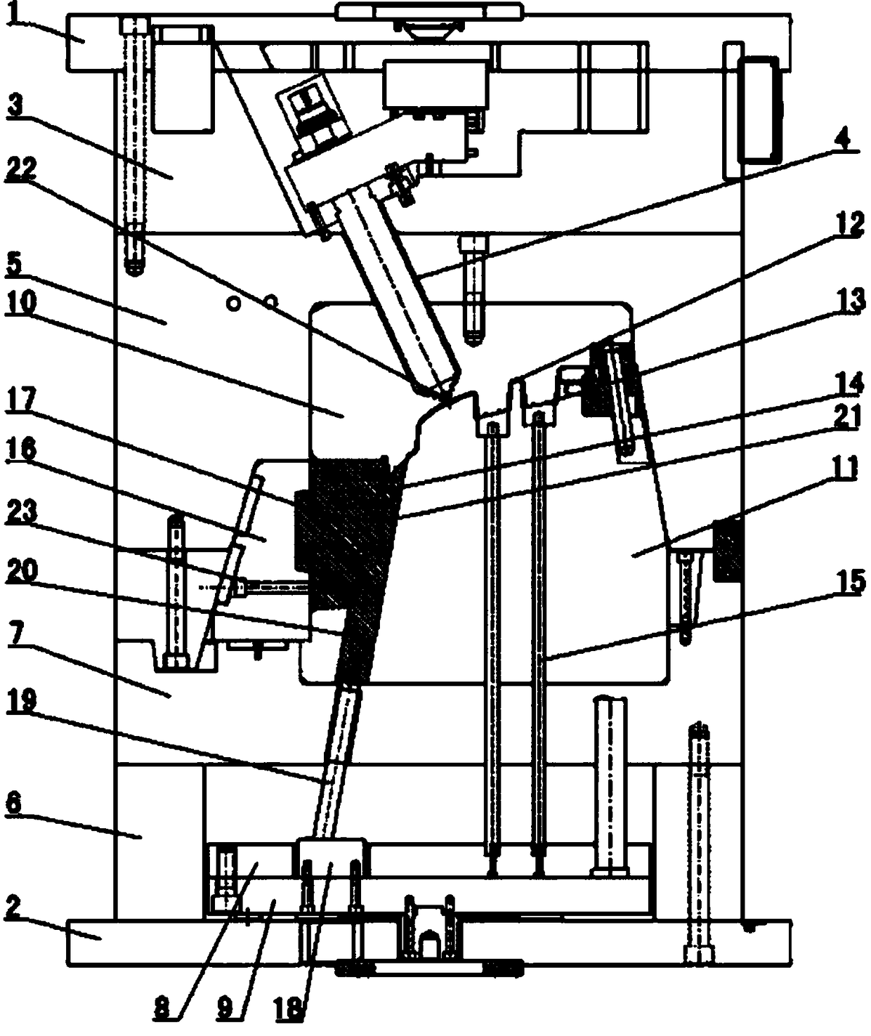
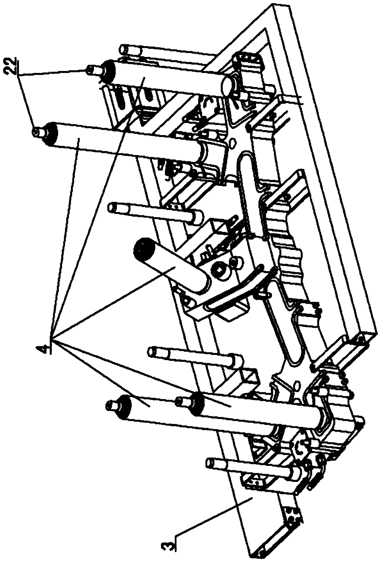
[0009] The invention relates to a splicing combined demoulding mechanism for the front grille mold of an automobile, such as figure 1 , figure 2 As shown, it includes the upper template 1 and the lower template 2 of the mold, the runner plate 3 is installed under the upper template, the hot runner nozzle 4 is installed in the runner plate, the fixed template 5 is installed under the runner plate, and the fixed mold insert 10 is installed in the fixed template , the mold foot 6 is installed on the lower template 2, the movable template 7 is installed on the mold foot, the movable mold insert 11 is installed in the movable template, and there is an injection-molded front grille 12 between the movable mold insert 11 and the fixed mold insert 10, The back side of the front grille is provided with installation buckles 13 and undercuts 14, an upper top plate 8 and a lower top plate 9 are arranged between the die feet 6, the upper top plate 8 is connected with a straight ejector rod...


PUM


Abstract

The invention discloses a splicing type combination demolding mechanism for a front grill mold of an automobile. The splicing type combination demolding mechanism comprises an upper mold plate and a lower mold plate. A runner plate is mounted at the lower part of the upper mold plate. A hot runner nozzle is mounted in the runner plate. A fixed mold plate is mounted at the lower part of the runnerplate. A fixed mold insert is mounted in the fixed mold plate. Support blocks are mounted on the lower mold plate. A movable mold plate is mounted on the support blocks. A movable mold insert is mounted in the movable mold plate. A front grill formed through injection moulding is arranged between the movable mold insert and the fixed mold insert. A mounting buckle and an inverted buckle are arranged on the back side of the front grill. An upper top plate and a lower top plate are arranged between the support blocks. A straight ejector rod is connected onto the upper top plate. The top of the straight ejector rod is matched with the mounting buckle. An outer sliding block is arranged on one side of the movable mold plate. An inner insert is spliced on the inner wall of the outer sliding block. An inclined sliding seat is mounted on the upper top plate. An inclined ejector rod is connected onto the inclined sliding seat. An inclined top insert is mounted on the inclined ejector rod. Theinclined top insert is matched with the inverted buckle. A side edge mold cavity of the front grill is formed between the inclined top insert and the inner insert. A front grill side edge is arrangedin the side edge mold cavity.

Description

technical field [0001] The invention relates to a splicing combined demoulding mechanism for an automobile front grille mold, which belongs to the field of injection molds. Background technique [0002] The front grille of radiator is a grid-shaped part for cooling and ventilation of automobile engine, which plays the role of protection, heat dissipation, ventilation and exterior decoration of automobile parts. Since the grille is located in the most prominent position at the front of the car, the requirements for its appearance quality are very high. However, because the area of ​​the front grille is relatively large, and there are many mesh holes on the front grille, at present, single-point pouring is often used in injection molding, but it is difficult to control the flow rate and material flow rate of single-point pouring. Flow time, resulting in unbalanced pouring, insufficient injection molding, prone to insufficient filling, mesh area deformation, air trapping, weld...

Claims


Application Information

Patent Timeline
Patent Type & Authority Applications(China)
IPC IPC(8): B29C45/27B29C45/33B29C45/40B29C45/44B29L31/30
CPCB29C45/27B29C45/33B29C45/4005B29C45/4435B29C2045/4063B29C2045/445B29L2031/30
Inventor 张新鹏
Owner 余姚市宏硕模具制造有限公司
Why Eureka
Try Eureka