

Four-line-box blackboard optical projection device adjustable in angle
An optical projection and adjustable technology, applied in the field of projection, can solve the problems of poor heat dissipation and dehumidification, non-adjustable angle, inconvenient use, etc., achieve the effect of convenient and fast projection angle, prevent moisture damage, and prolong service life
- Summary
- Abstract
- Description
- Claims
- Application Information
AI Technical Summary
Problems solved by technology
Method used
Image

Examples
Embodiment Construction
[0025] The following will clearly and completely describe the technical solutions in the embodiments of the present invention with reference to the accompanying drawings in the embodiments of the present invention. Obviously, the described embodiments are only some, not all, embodiments of the present invention.
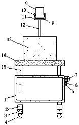
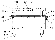
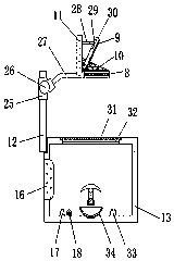
[0026] refer to Figure 1-4 , an angle-adjustable four-line grid blackboard optical projection device, including a hollow base 1, the four corners of the bottom outer wall of the base 1 are connected with lifting hydraulic cylinders 2 by fastening bolts, and the four lifting hydraulic cylinders 2 are far away from the end of the base 1 All are connected with supporting legs 3 by fastening bolts, and the bottoms of the four supporting legs 3 are all connected with universal wheels 4 by fastening bolts, and the four corners of the outer wall of the top of the base 1 are provided with installation grooves 20, and the bottoms of the four installation grooves 20 The inner...
PUM
 Abstract
Description
Claims
Application Information