Bearing buffer mechanism for plow discharger

A plow unloader and buffer mechanism technology, applied in the direction of conveyor objects, transportation and packaging, etc., can solve the problems of easy material leakage, poor buffer effect, wear of plowshares and conveyor belts, etc., to prolong service life and reduce leakage The risk of material, the effect of reducing friction

Inactive Publication Date: 2018-06-01
江苏日升电力机械有限公司
View PDF14 Cites 6 Cited by
  • Summary
  • Abstract
  • Description
  • Claims
  • Application Information

AI Technical Summary

Problems solved by technology

[0006] Aiming at the deficiencies of the prior art, the present invention provides a load-bearing buffer mechanism for a plow unloader, whi

Method used


Image

  • Bearing buffer mechanism for plow discharger
  • Bearing buffer mechanism for plow discharger

Examples


Embodiment Construction

[0017] The following will clearly and completely describe the technical solutions in the embodiments of the present invention with reference to the accompanying drawings in the embodiments of the present invention. Obviously, the described embodiments are only some, not all, embodiments of the present invention. Based on the embodiments of the present invention, all other embodiments obtained by persons of ordinary skill in the art without making creative efforts belong to the protection scope of the present invention.

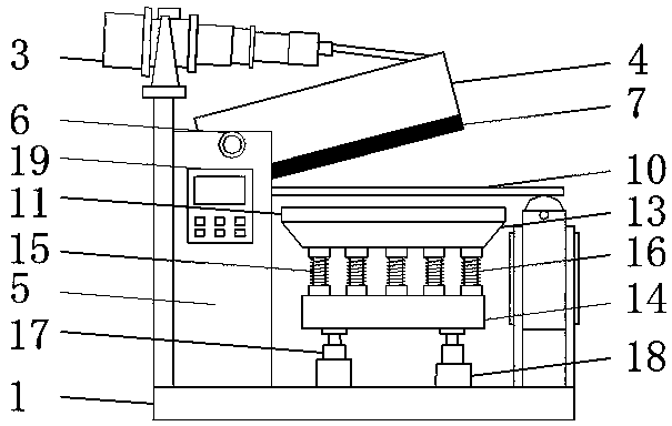
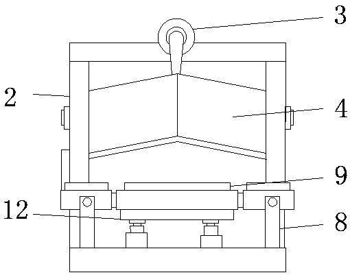
[0018] Such as Figure 1-2 As shown, the present invention provides a technical solution: a load-bearing buffer mechanism for a plow unloader, including a support base plate 1, a frame 2, an electro-hydraulic push rod 3 and a support buffer mechanism 12, and one side of the upper surface of the support base plate 1 is set There is a frame 2, and an electro-hydraulic push rod 3 is installed on the frame 2. One end of the electro-hydraulic push rod 3 is connecte...


PUM


Abstract

The invention discloses a bearing buffer mechanism for a plow discharger. The bearing buffer mechanism comprises a support bottom plate, a rack, an electric-hydraulic push rod and a support buffer mechanism, wherein the rack is arranged on one side of the upper surface of the bottom plate, the electric-hydraulic push rod is installed on the rack, a plowshare is connected to one end of the electric-hydraulic push rod, both sides of one end of the plowshare are hinged with two vertical plates arranged on the support bottom plate respectively by virtue of hinged seats, a cushion is bonded to thebottom of the plowshare, a rotating roller frame is arranged on one side, which is opposite to the rack, of the upper surface of the support bottom plate, a rotating roller is installed on the rotating roller frame, a conveying belt is arranged on the rotating roller, a support plate is arranged just below the conveying belt, the support buffer mechanism is arranged at the bottom of the support plate, and the support buffer mechanism comprises an upper fixed block, a lower fixed block, a support rod and a buffer spring. The bearing buffer mechanism has buffer and support effects on a conveyingmechanism, material leakage is difficult during discharge, and the wear of the mechanism is less.

Description

technical field [0001] The invention relates to the technical field of auxiliary equipment for a plow unloader, in particular to a load-bearing buffer mechanism for a plow unloader. Background technique [0002] The plow unloader uses the electro-hydraulic push rod as the power source. When working, the push rod extends the drive rod to drive the frame forward to complete the drop of the machine head, and supports the flat idler to make the working surface of the tape straight. The lower edge of the head is closely attached to the tape surface, and the materials on the tape are unloaded into the hopper and sent to the required place. After the unloading is completed, the electro-hydraulic push rod is activated to retract the drive rod, driving the frame back, and the plowshare is lifted up. The variable idler group changes from parallel to groove shape, allowing materials to pass through smoothly. [0003] However, the existing load-bearing buffer mechanism for plow unloade...

Claims


Application Information

Patent Timeline
IPC IPC(8): B65G47/76
CPCB65G47/76
Inventor 徐日平
Owner 江苏日升电力机械有限公司
Why Eureka
Try Eureka