Eureka AIR delivers breakthrough ideas for toughest innovation challenges, trusted by R&D personnel around the world.

Pushing device

A technology of pushing device and installation panel, which is applied in transportation and packaging, conveyor objects, etc., can solve the problems of easily crushing fingers, time-consuming and labor-intensive, worker burns, etc., so as to improve work safety and improve feeding efficiency. , The effect of high installation stability

Inactive Publication Date: 2018-06-01
惠州恒立信科技有限公司
View PDF0 Cites 0 Cited by
  • Summary
  • Abstract
  • Description
  • Claims
  • Application Information

AI Technical Summary

Problems solved by technology

[0002] Now the factory is manufacturing some workpieces, there are some feeding problems in high temperature environment, the traditional feeding is manual pushing, the whole process is manual operation, because in high temperature, manual pushing is easy to cause burns to workers, and workers In the process of pushing, due to the weight of the workpiece itself, it is easy to crush the fingers and cause work-related injuries
The current technology mostly uses manual push. Although the material can be pushed to the preset position to complete the push work, the manual push method has the disadvantages of low efficiency, high cost, time-consuming and labor-intensive, and is prone to accidents. It is necessary to provide a safe and automatic pushing device so as to avoid the defects caused by manual operation, save time, labor and high efficiency, and avoid accidental injuries to workers

Method used


Image

  • Pushing device

Examples


Embodiment Construction

[0018] In order to facilitate the understanding of the present invention, the present invention will be described more fully below with reference to the associated drawings. Preferred embodiments of the invention are shown in the accompanying drawings. However, the present invention can be embodied in many different forms and is not limited to the embodiments described herein. On the contrary, the purpose of providing these embodiments is to make the disclosure of the present invention more thorough and comprehensive.

[0019] It should be noted that when an element is referred to as being “fixed” to another element, it can be directly on the other element or there can also be an intervening element. When an element is referred to as being "connected to" another element, it can be directly connected to the other element or intervening elements may also be present. The terms "vertical," "horizontal," "left," "right," and similar expressions are used herein for purposes of ill...


PUM


Abstract

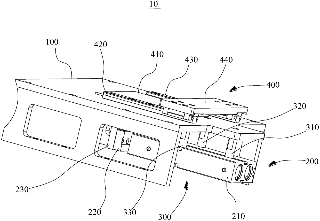
The invention discloses a pushing device which comprises a mounting panel, a pushing driving assembly, a connecting assembly and a pushing assembly; the pushing driving assembly is connected with themounting panel through the connecting assembly; the pushing assembly is in driving connection with the pushing driving assembly; the pushing assembly comprises a pushing driving part, a connecting block and a telescopic block; the pushing driving part is in driving connection with the connecting block; and the telescopic block is arranged on the connecting block. According to the pushing device, the mounting panel, the pushing driving assembly, the connecting assembly and the pushing assembly are adopted, the mounting panel is used for fixedly mounting the pushing driving assembly, the pushingdriving assembly is used for driving the pushing assembly, and the connecting assembly is used for connecting with the pushing driving assembly and the mounting panel, so that the mounting stabilityof the pushing driving assembly is higher; the pushing assembly is used for pushing materials to a preset position, and traditional manual material pushing is replaced by mechanical material pushing,so that a worker is prevented from being burnt, the operating working safety of the worker is improved, and the charging efficiency is improved.

Description

technical field [0001] The invention relates to the technical field of pushing materials, in particular to a pushing device. Background technique [0002] Now the factory is manufacturing some workpieces, there are some feeding problems in high temperature environment, the traditional feeding is manual pushing, the whole process is manual operation, because in high temperature, manual pushing is easy to cause burns to workers, and workers In the process of pushing, due to the weight of the workpiece itself, it is very easy to crush the fingers and cause work-related injuries. The current technology mostly uses manual push. Although the material can be pushed to the preset position to complete the push work, the manual push method has the disadvantages of low efficiency, high cost, time-consuming and labor-intensive, and is prone to accidents. It is necessary to provide a safe and automatic material pushing device, so as to avoid the defects generated in the manual operation...

Claims


Application Information

Patent Timeline
Patent Type & Authority Applications(China)
IPC IPC(8): B65G47/82
CPCB65G47/82
Inventor 刘礼军
Owner 惠州恒立信科技有限公司
Why Eureka
Eureka Blog
Learn More