Lock connecting rod

A connecting rod and connecting lock technology, applied in handle connection, building locks, door/window accessories, etc., can solve problems such as increasing work difficulty, installing parts in place, and connecting hands and lock bodies.

Pending Publication Date: 2018-06-01
李浩远
View PDF5 Cites 5 Cited by
  • Summary
  • Abstract
  • Description
  • Claims
  • Application Information

AI Technical Summary

Problems solved by technology

This may lead to the following problems in actual use: 1. The connecting rod needs to be cut, which increases the processing procedure during installation and increases the difficulty of work; 2. Due to the different specifications or installation dimensions, the length of the connecting rod is cut The requirements are very high. If the length after cutting is longer, the parts cannot be instal

Method used


Image

  • Lock connecting rod
  • Lock connecting rod
  • Lock connecting rod

Examples


Embodiment Construction

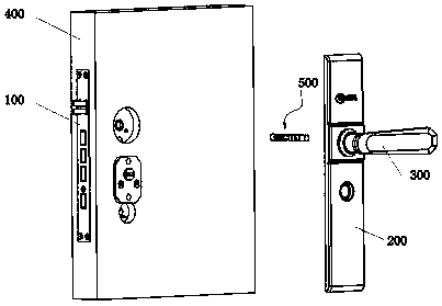
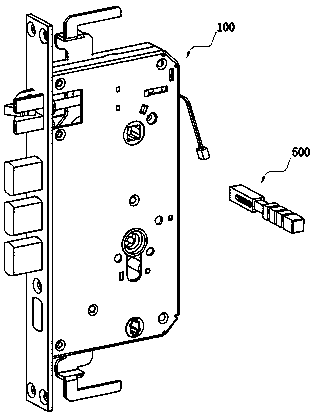
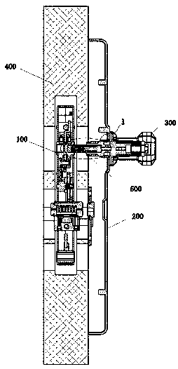
[0026] As attached figure 1 And figure 2 The door lock shown includes a lock body 100, a panel 200, and a handle 300. The lock body 100 is installed in the door panel 400, the panel 200 is installed on the outside of the door panel 400, the handle 300 is installed on the panel 200, and the handle 300 It is linked to the lock body 100 through a connecting rod 500.

[0027] The connecting rod 500 includes a first connecting rod 1, a second connecting rod 2 and an elastic member 3. The first end of the first connecting rod 1 is fixedly connected to the lock body 100 in the circumferential direction (generally, the first end of the first connecting rod 1 is made into a square shape, and the lock body 100 correspondingly has a square hole. The connecting rod 1 is directly inserted into the square hole to achieve circumferential fixation), the first end of the second connecting rod 2 is fixedly connected to the handle 300 in the circumferential direction, and the second end of the fir...


PUM


Abstract

The invention relates to a lock connecting rod which comprises a lock and a handle. The handle is connected with the lock through the connecting rod in a linked manner, the locking rod comprises a first connecting rod, a second connecting rod and an elastic part, a first end of the first connecting rod is circumferentially and fixedly connected on the lock, a first end of the second connecting rodis circumferentially and fixedly connected on the handle, a second end of the first connecting rod is abutted to a second end of the second connecting rod, the first connecting rod and the second connecting rod can axially and relatively move, and the elastic part is mounted between the first connecting rod and the second connecting rod. The lock connecting rod has the advantages that the elasticpart is corporately extruded by the first connecting rod and the second connecting rod, so that the elastic part axially and relatively moves, the connecting rod is actually shortened when being placed at the mounting position to adapt to needed mounting sizes, disassembling and re-cutting of components are omitted, mounting processes are saved, and the connecting rod is simple in structure.

Description

Technical field [0001] The invention relates to a connecting rod of a lock. Background technique [0002] The main components of the anti-theft door lock include the lock body, the inner panel, the outer panel, the inner handle and the outer handle. The lock body is installed in the door panel. The inner panel and the outer panel are respectively installed on the inner and outer sides of the door panel. The inner handle and the outer handle correspond to each other. Installed on the inner and outer panels, the inner handle and the outer handle are respectively linked to the lock body through a connecting rod (square steel). The rotation of the inner handle or the outer handle drives the corresponding connecting rod to rotate, so that the connecting rod drives the lock The transmission mechanism in the body makes the corresponding actions of unlocking or locking. [0003] In order to adapt to various specifications or installation dimensions, such as the thickness of the door panel...

Claims


Application Information

Patent Timeline
IPC IPC(8): E05B3/00E05B15/00
CPCE05B3/00E05B15/0033
Inventor 李善德
Owner 李浩远
Why Eureka
Try Eureka