Crane beam and preparation method and application method thereof

A technology of traveling beams and connecting plates, applied in the directions of load suspension components, rail systems, transportation and packaging, etc., can solve the problems of insufficient support performance, great influence on weld quality, frequent vibration loads, etc., and achieve on-site construction operations. Convenience, saving installation program, simple structure setting effect

Inactive Publication Date: 2021-03-16
山东晟天钢构有限公司
View PDF5 Cites 0 Cited by
  • Summary
  • Abstract
  • Description
  • Claims
  • Application Information

AI Technical Summary

Problems solved by technology

However, the inertial force of the vehicle during operation is very large, and the simple form of the vehicle stop in the prior art cannot meet the requirements of use in terms of strength and firmness, especially at the two-span ends of the vehicle beam, because it cannot effectively resist Accidents often occur due to the impact of driving, which poses a threat to safe production
[0003] In addition, in the existing technology, the connection structure between the driving beam and the column is relatively complicated, and the direct welding of the tie rod and the column is used, which destroys the performance of the driving beam and the base material of the column; at the same time, the driving beam crane has a live load, and the vibration load is frequent. The seam quality has a great influence, its safety and practicality are not reliable enough, and its supporting performance is not high enough

Method used


Image

  • Crane beam and preparation method and application method thereof
  • Crane beam and preparation method and application method thereof
  • Crane beam and preparation method and application method thereof

Examples


Embodiment

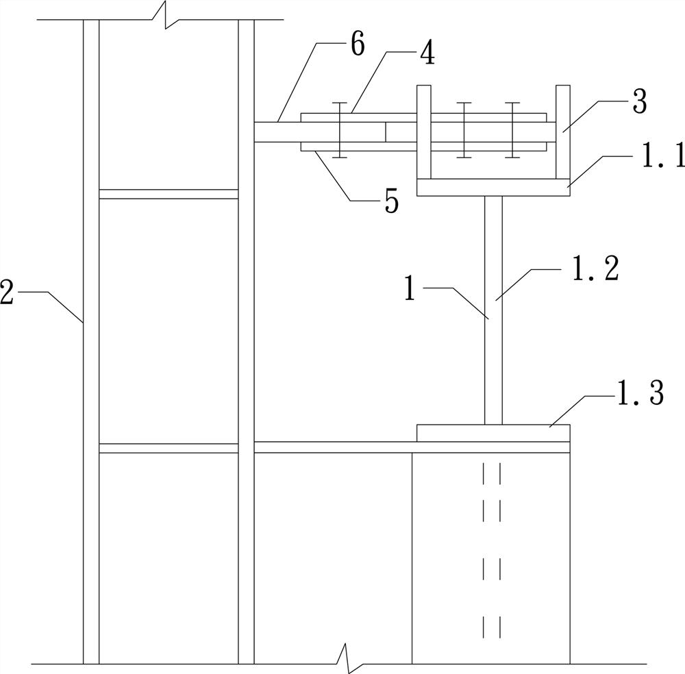
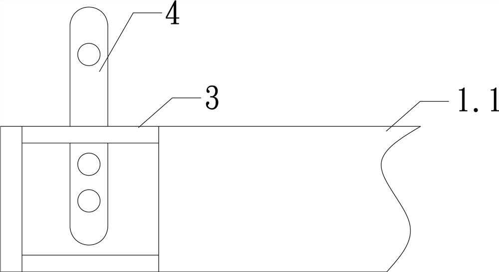
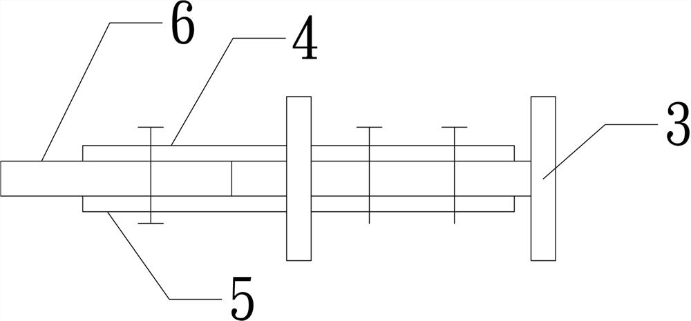
[0031] Such as Figure 1-3 As shown, the driving beam includes a driving beam body 1, a driving beam end mounting frame 2, an end I-beam 3, a connecting plate A4, a connecting plate B5 and a connecting plate C6, and the two ends of the driving beam body 1 Respectively supported on the corresponding driving beam end mounting frame 2, the driving beam end mounting frame 2 includes a vertical column 2.1, and the top of the vertical column 2.1 has a horizontally arranged corbel support 2.2, and the driving beam end The end of the body 1 is supported on the corbel support 2.2, and the upper surfaces of the two ends of the driving beam body 1 are respectively welded with an end I-beam 3, and a connecting plate is detachably installed on the end I-beam 3 A4 and the connecting plate B5, the top of the vertical column 2.1 has a connecting plate C6 connected with the connecting plate A4 and the connecting plate B5.

[0032] In this embodiment, the driving beam body 1 includes an upper ...


PUM


Abstract

The invention relates to a crane beam. Two ends of a crane beam body are separately supported on corresponding crane beam end mounting frames, each crane beam end mounting frame comprises a vertical stand column, the end of the crane beam body is supported on a bracket support, and end I-shaped steel is separately welded on the upper surfaces of two ends of the crane beam body. Connecting plates Aand connecting plates B are detachably installed on the end I-shaped steel, and connecting plates C connected with the connecting plates A and the connecting plates B are arranged at the tops of thevertical stand columns. The invention further provides a preparation method of the crane beam. The invention further provides a using method of the crane beam. The crane beam and the preparation method and application method thereof have the following beneficial effects that the structure arrangement is simpler, and the on-site construction operation is more convenient; installation procedures between the crane beam and a steel column on a construction site are omitted, and the labor intensity of constructors is reduced; and the end I-shaped steel serves as a car stop mechanism and can effectively prevent inertia advancing of driving, and safety production is guaranteed.

Description

technical field [0001] The invention relates to a driving beam, a preparation method and a using method thereof, and belongs to the technical field of driving erection. Background technique [0002] Cranes are widely used in various occasions. Using cranes for operations can not only effectively improve production efficiency, but also benefit production safety. However, the inertial force of the vehicle during operation is very large, and the simple form of the vehicle stop in the prior art cannot meet the requirements of use in terms of strength and firmness, especially at the two-span ends of the vehicle beam, because it cannot effectively resist Accidents often occur due to the impact of driving, which poses a threat to safe production. [0003] In addition, in the existing technology, the connection structure between the driving beam and the column is relatively complicated, and the direct welding of the tie rod and the column is used, which destroys the performance of ...

Claims


Application Information

Patent Timeline
Patent Type & Authority Applications(China)
IPC IPC(8): B66C7/00B66C7/16B23P15/00
CPCB66C7/00B66C7/16B23P15/00
Inventor 李亚刘文明田国军
Owner 山东晟天钢构有限公司
Why Eureka
Try Eureka