Quick dismounting and connecting mechanism for impeller and fan motor as well as air conditioner

A fan motor and connecting mechanism technology, which is applied in air conditioning systems, machines/engines, mechanical equipment, etc., can solve the problems of fan motor damage, complicated disassembly, and smaller force surface for installation, and achieve high connection strength, reliable transmission, big effect

Pending Publication Date: 2018-08-03
GREE ELECTRIC APPLIANCES INC
View PDF11 Cites 1 Cited by
  • Summary
  • Abstract
  • Description
  • Claims
  • Application Information

AI Technical Summary

Problems solved by technology

[0002] The air conditioner is a commonly used household appliance. The air duct and water channel system of the traditional air conditioner are integrated with the bottom shell. As the basic parts, the air conditioner is first assembled and fixed. It is extremely inconvenient to take it out for cleaning after disassembly
[0003] During the long-term use of the air conditioner, the dust and other debris entering the air duct and water channel from the air inlet will cause serious pollution to the entire air duct and water channel system. If it is not cleaned in time, it will be used as a pollution source to bring harm to the environment during the operation of the air conditioner. important to the user's health
[0004] In order to facilitate disassembly and washing, the patent No. CN205037533U discloses a shell of an air conditioner indoor unit and an air conditioner indoor unit with it, which includes an upper chassis, a lower chassis, and a guide assembly, and the mask is detachably installed on the upper chassis. , the heat exchanger is installed on the upper chassis, and the fan is detachably installed on the lower chassis. In the above-mentioned prior art, the heat exchanger is a water channel, and the fan blades below the heat exchanger form an air channel, and the fan is fixedly connected to the fan blades. The rotation of the fan drives the blades to rotate. Therefore, when disassembling in the prior art, the fan and the blades need to be disassembled together to clean the pollutants in the blades. In this disassembly method, the fan motor assembly and the air duct components need to be disassembled together. Down cleaning, which has the following problems: when cleaning, it is easy to make sewage enter the fan motor part connected to the fan blade, and the fan motor will be damaged by water ingress
However, in this prior art, it is troublesome to disassemble the fan blade and the fan motor. It is necessary to remove the screw first, and then remove the reinforcing ring to remove the fan blade connected to the fan motor. That is, the disassembly of the fan blade and the fan motor is complicated.
[0006] In order to solve the above technical problem of complicated disassembly, Chinese patent CN2823621Y discloses a fan device for household appliances, which includes a coupling device, which includes a fan blade embedded in the center of the other end surface of the impeller and The motor shaft sleeve fixedly installed on the main shaft of the driving fan motor, one or more installation slots are arranged in the fan blade nest, and one or more installation cards are provided on the motor shaft sleeve, in order to facilitate the installation of the card smoothly inserted into the installation groove, in the above prior art, guide slopes are provided on both sides of the top of the installation card, that is, guide slopes are also provided on the side of the force surface, and in order to prevent the guide slope from becoming the force surface The sleeve has a counteracting force that is opposite to the axial force toward the fan motor generated by the force surface when it rotates. The guide slope does not conflict with the installation groove, that is to say, the guide slope cannot become the force surface, so in limited In the installation groove of the same depth in the space, the force surface of the installation card becomes smaller, and the connection strength is correspondingly smaller

Method used


Image

  • Quick dismounting and connecting mechanism for impeller and fan motor as well as air conditioner
  • Quick dismounting and connecting mechanism for impeller and fan motor as well as air conditioner
  • Quick dismounting and connecting mechanism for impeller and fan motor as well as air conditioner

Examples


Embodiment Construction

[0037] The technical solutions of the present invention will be clearly and completely described below in conjunction with the accompanying drawings. Apparently, the described embodiments are some of the embodiments of the present invention, but not all of them. Based on the embodiments of the present invention, all other embodiments obtained by persons of ordinary skill in the art without making creative efforts belong to the protection scope of the present invention.

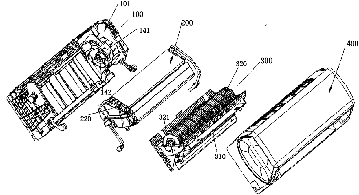
[0038] figure 1 Shown is a modular air conditioner indoor unit according to the present invention, which includes a base module 100 , a heat exchange module 200 , an air flow channel module 300 and an appearance module 400 .

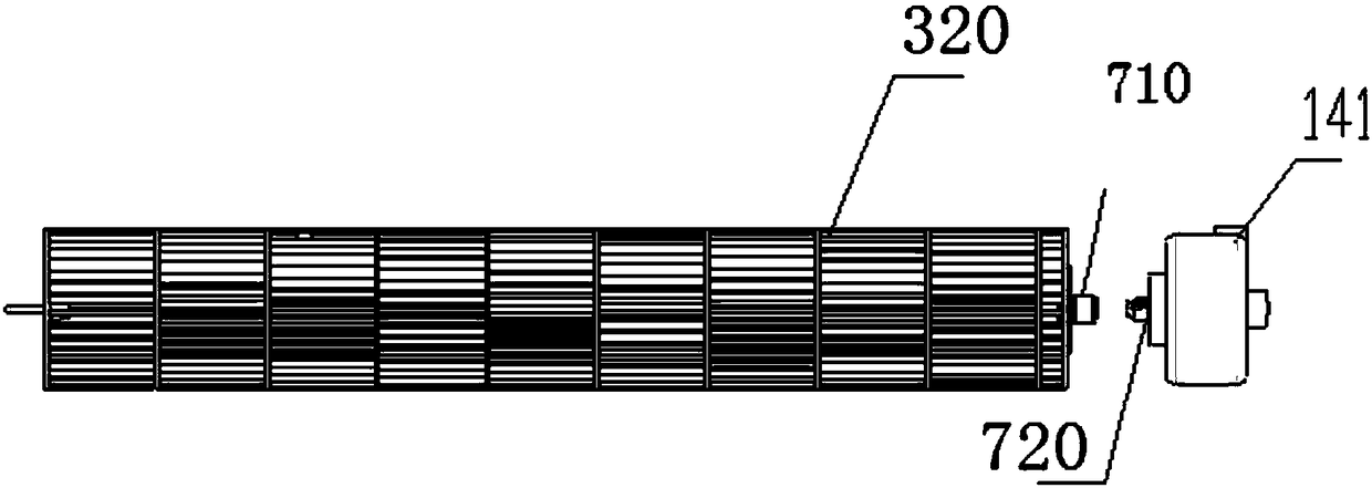
[0039] The air channel module 300 includes an air channel assembly 301, and the impeller assembly in the air channel assembly 301, such as figure 2As shown, it includes an impeller 320 having an impeller shaft 321 , one end of the impeller shaft 321 close to the fan motor 141 is in tra...


PUM


Abstract

The invention relates to the technical field of air conditioners, in particular to a quick dismounting and connecting mechanism for an impeller and a fan motor. The quick dismounting and connecting mechanism comprises a fan inserting sleeve and a motor shaft sleeve, wherein the fan inserting sleeve is fixedly connected with an impeller shaft of the impeller; the motor shaft sleeve is matched withthe fan inserting sleeve, and is fixedly connected with the output shaft of the fan motor; the fan inserting sleeve is provided with a transmission side surface which is matched with the motor shaft sleeve while rotating in a transmission direction that the fan motor drives the impeller to rotate; the transmission side surface applies axial force towards the fan motor to the motor shaft sleeve; and the fan inserting sleeve and the transmission side surface on the motor shaft sleeve extend along the completely axially superposed portion during mutual sleeving. In order to solve the technical problems that force applying surfaces with mounting cards in mounting slots of the same depth in a limited space in the prior art are small, and connecting strength is small, the invention provides thequick dismounting and connecting mechanism for the impeller and the fan motor, and the quick dismounting and connecting mechanism is great in force applying surface and is great in connecting strength.

Description

technical field [0001] The invention relates to the technical field of air conditioners, in particular to a quick-disconnect connection mechanism for an impeller and a fan motor and an air conditioner thereof. Background technique [0002] The air conditioner is a commonly used household appliance. The air duct and water channel system of the traditional air conditioner are integrated with the bottom shell. As the basic parts, the air conditioner is first assembled and fixed. It is extremely inconvenient to disassemble and clean it after disassembly. [0003] During the long-term use of the air conditioner, the dust and other debris entering the air duct and water channel from the air inlet will cause serious pollution to the entire air duct and water channel system. If it is not cleaned in time, it will be used as a pollution source to bring harm to the environment during the operation of the air conditioner. It is of great significance to the user's health. [0004] In o...

Claims


Application Information

Patent Timeline
Patent Type & Authority Applications(China)
IPC IPC(8): F04D29/28F04D29/05F04D29/62F04D25/08F24F1/00
CPCF04D25/08F04D29/05F04D29/282F04D29/601F04D29/626F24F1/0022F04D17/04
Inventor 汪春节杨盼郭瑞水冯绍广胡保国
Owner GREE ELECTRIC APPLIANCES INC
Why Eureka
Try Eureka