Clamp body for rail traffic vehicle braking system

A rail transit vehicle and braking system technology, which is applied in the field of braking equipment, can solve problems such as high operating costs, difficult maintenance, and weak structural strength, and achieve improved reliability and stability, good load-carrying and positioning capabilities, and flexible use convenient effect

Active Publication Date: 2018-06-01
WUHU JINMAO FLUID TECH CO LTD
View PDF15 Cites 0 Cited by
  • Summary
  • Abstract
  • Description
  • Claims
  • Application Information

AI Technical Summary

Problems solved by technology

[0002] At present, with the development of urbanization and the advancement of transportation technology, rail vehicles such as subways and light rails have been widely used. The clamps in the braking equipment used in various rail vehicles are often used. Although the structure can meet the needs of use, the overall structure is complex, the processing and maintenance are difficult, and the cost is high. At the same time, there are still shortcomings such as relatively weak structural strength, poor bearing capacity and impact resistance, which lead to the current rail transit. When the brake is in operation, on the one hand, the operating cost is high and the maintenance is difficult. On the other hand, it is easy to cause the braking force output stability of the rail vehicle to be relatively poor, which not only seriously affects the braking reaction distance, but also As a result, the stability and comfort of the vehicle are greatly affected when braking. Therefore, in view of this phenomenon, it is urgent to develop an inventive rail transit brake caliper structure to meet the needs of actual use.

Method used


Image

  • Clamp body for rail traffic vehicle braking system
  • Clamp body for rail traffic vehicle braking system

Examples


Embodiment Construction

[0014] In order to make the technical means, creative features, goals and effects achieved by the present invention easy to understand, the present invention will be further described below in conjunction with specific embodiments.

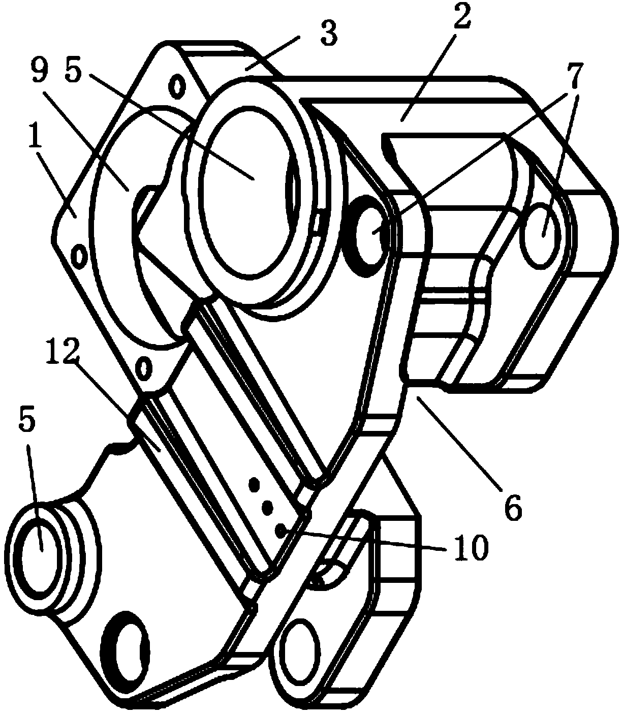
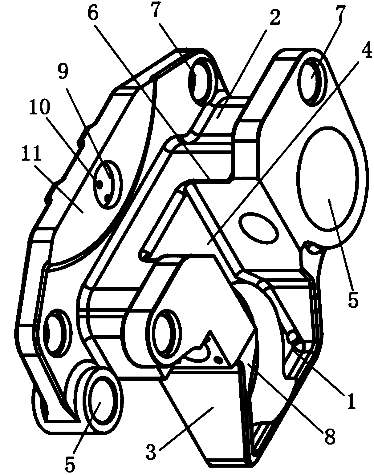
[0015] Such as figure 1 and 2 The clamp body for the braking system of a rail transit vehicle includes a connecting plate 1, a positioning slot 2 and a reinforcing rib plate 3, the connecting plate 1, the positioning slot 2 and the reinforcing rib plate 3 are of an integrated structure, and the connecting plate 1 The lower end surface is connected to the upper end surface of the positioning slot 2, and the axis of the connecting plate 1 and the axis of the positioning slot 2 are distributed parallel to each other. The distance between the axis of the connecting plate 1 and the axis of the positioning slot 2 is 0-20 mm, and the width of the positioning slot 2 is 3-5 times the width of the plate 1, the reinforcing rib plate 3 is connected to the re...


PUM


Abstract

The invention relates to a clamp body for a rail traffic vehicle braking system. The clamp body for the rail traffic vehicle braking system comprises a connection plate, a positioning clamping grooveand reinforcing rib plates. The connection plate, the positioning clamping groove and the reinforcing rib plates are of an integrated structure. The lower end face of the connection plate is connectedwith the upper end face of the positioning clamping groove. The reinforcing rib plates are connected with the rear surface of the connection plate and the upper end face of the positioning clamping groove. The side surfaces of the reinforcing rib plates and the side surface of the connection plate are distributed in a parallel and level manner, and the reinforcing rib plates and the connection plate jointly form a guide groove with a rectangular cross section. The left end and the right end of the upper end face are each provided with a connection axle hole. The top of the side surface, corresponding to the guide groove, of the connection plate is provided with a first positioning hole. The position, corresponding to the guide groove, of the rear surface of the front side face of the positioning clamping groove is provided with a second positioning hole. The clamp body for the rail traffic vehicle braking system is simple in structure and flexible and convenient to use, the installation and changing operation efficiency is high, good bearing and positioning capacities are achieved, the reliability and the stability of the braking system running can be effectively improved, and theoutput torque of braking force and the stability of braking force output are advantageously improved.

Description

technical field [0001] The invention relates to a brake device, specifically a clamp body for a rail vehicle brake system. Background technique [0002] At present, with the development of urbanization and the advancement of transportation technology, rail vehicles such as subways and light rails have been widely used. The clamps in the braking equipment used in various rail vehicles often use the traditional Although the structure can meet the needs of use, the overall structure is complex, the processing and maintenance are difficult, and the cost is high. At the same time, there are still shortcomings such as relatively weak structural strength, poor bearing capacity and impact resistance, which lead to the current rail transit. When the brake is in operation, on the one hand, the operating cost is high and the maintenance is difficult. On the other hand, it is easy to cause the braking force output stability of the rail vehicle to be relatively poor, which not only serio...

Claims


Application Information

Patent Timeline
Patent Type & Authority Applications(China)
IPC IPC(8): F16D65/04B61H7/12
CPCB61H7/12F16D65/04
Inventor 孙述全孙雄高峰
Owner WUHU JINMAO FLUID TECH CO LTD
Why Eureka
Try Eureka