
Gardening landscape lamp

A landscape lighting and garden technology, applied in the field of garden landscape lighting, can solve problems such as hidden safety hazards, screws and nuts easily tripping pedestrians, etc.

Active Publication Date: 2018-06-01
瑞安市森威家用电器有限公司
View PDF5 Cites 0 Cited by
  • Summary
  • Abstract
  • Description
  • Claims
  • Application Information

AI Technical Summary

Problems solved by technology

[0002] Garden landscape lights are commonly used lighting devices in parks. They generally include a lampshade, a column and an anchor rod installed at the lower end of the column. The lampshade is fixed to the upper end of the column through several diagonal bars distributed in the circumferential direction; The upper end of the rod is fixed with a support plate, and four screws are arranged on the upper surface of the support plate, and the lower end of the column is fixed with a bottom plate, and a through hole is arranged in the bottom plate. When the column and the anchor rod are fixed, the screws on the support plate pass through the bottom plate The through hole in the hole, and the nut is installed on the screw, after the nut and the screw are locked, the fixing of the column and the anchor can be realized; however, after the column and the anchor in the current garden landscape lights are fixed, the screw and the anchor The nuts are exposed, so that when pedestrians pass by the landscape lights, the exposed screw rods and nuts are easy to trip pedestrians, which poses a great safety hazard

Method used


Image

  • Gardening landscape lamp
  • Gardening landscape lamp
  • Gardening landscape lamp

Examples


Embodiment Construction

[0019] The specific embodiments of the present invention will be further described in detail below in conjunction with the accompanying drawings.

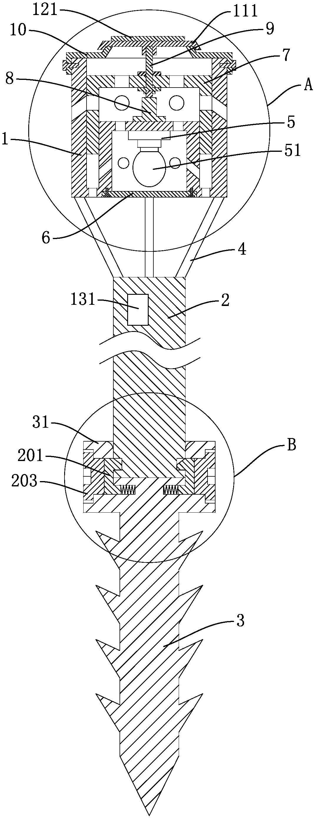
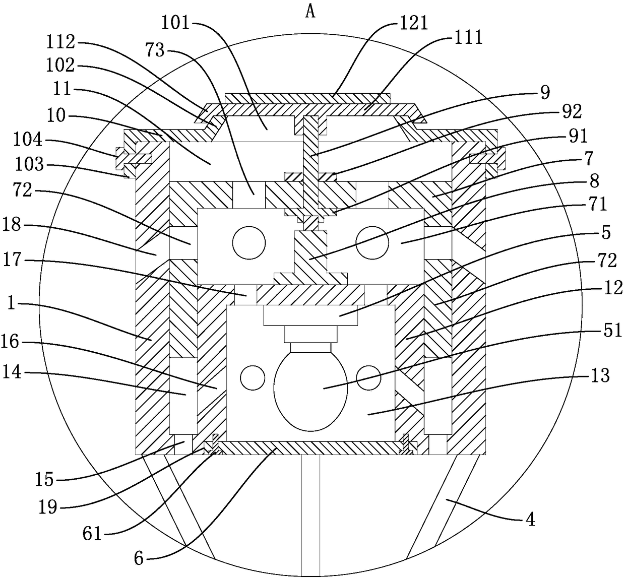
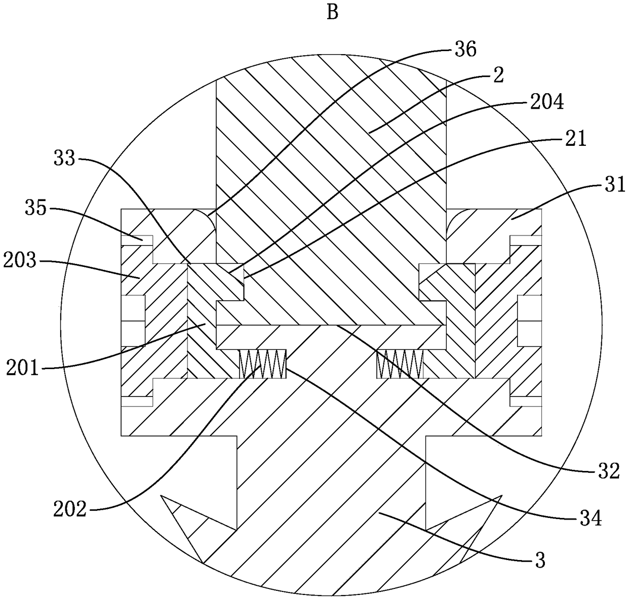
[0020] A garden landscape lamp, comprising a lampshade 1, a column 2 and an anchor rod 3 installed at the lower end of the column 2, the lampshade 1 is fixed to the upper end of the column 2 through several diagonal rods 4 distributed in the circumferential direction, and the upper end of the lampshade 1 is provided with an opening The cavity 11 of the lampshade 1 is provided with an upward boss 12 in the middle of the lower end of the lampshade 1. A concave cavity 13 with an open lower end is arranged in the convex platform 12. A lamp holder 5 is fixed on the inner top of the concave cavity 13, and a lamp holder 5 is installed on the lamp holder 5. The light bulb 51 is equipped with a light guide plate 6 at the bottom of the concave cavity 13, and an annular groove 14 is formed between the boss 12 and the inner wall of the lampshad...


PUM


Abstract

The invention discloses a gardening landscape lamp. The gardening landscape lamp comprises a lampshade, an upright post and an anchor rod which is installed at the lower end of the upright post; the lampshade is fixed to the upper end of the upright post through a plurality of oblique rods which are distributed in the circumferential direction; the upper end of the anchor rod is provided with a supporting platform; the top of the supporting platform is provided with an inserting hole; the sidewall of the supporting platform is provided with a through hole communicating with the inserting hole;a [-shaped clamping part used for clamping the anchor rod and the upright post is arranged inside the through hole; the outer sidewall of the upright post is provided with an annular clamping slot for clamping one end of the clamping part; the inner sidewall of the supporting platform is provided with a slide way for inserting the other end of the clamping part; a spring is embedded between the slide way and the end part of the clamping part; the outer end part of the through hole is in threaded connection with a screw used for jacking the clamping part so as to make the clamping part lock the anchor rod and the upright post; and the outer end part of the through hole is provided with a countersunk head part for embedding the screw. By adopting the structure, the gardening landscape lampdisclosed by the invention can prevent occurrence of the phenomenon that a passerby is stumbled by the screw and eliminates potential safety hazards.

Description

technical field [0001] The invention belongs to the technical field of lighting devices and relates to a garden landscape lamp. Background technique [0002] Garden landscape lights are commonly used lighting devices in parks. They generally include a lampshade, a column and an anchor rod installed at the lower end of the column. The lampshade is fixed to the upper end of the column through several diagonal bars distributed in the circumferential direction; The upper end of the rod is fixed with a support plate, and four screws are arranged on the upper surface of the support plate, and the lower end of the column is fixed with a bottom plate, and a through hole is arranged in the bottom plate. When the column and the anchor rod are fixed, the screws on the support plate pass through the bottom plate The through hole in the hole, and the nut is installed on the screw, after the nut and the screw are locked, the fixing of the column and the anchor can be realized; however, af...

Claims


Application Information

Patent Timeline
Patent Type & Authority Applications(China)
IPC IPC(8): F21S8/08F21V17/16F21V17/12F21V23/00F21V29/83F21V31/00F21W131/109
CPCF21S8/081F21V17/12F21V17/164F21V23/003F21V29/83F21V31/00F21W2131/109
Inventor 沈惠萍
Owner 瑞安市森威家用电器有限公司
Learn More