Satellite clock error real-time prediction method based on phase jump

A satellite clock offset and phase hopping technology, which is applied to satellite radio beacon positioning systems, measuring devices, instruments, etc., can solve the problems that the clock offset cannot be accurately known, the real-time satellite clock jumps, and the normal operation of the positioning system is affected.

Inactive Publication Date: 2018-06-01
QIANXUN SI NETWORK ZHEJIANG CO LTD
View PDF6 Cites 27 Cited by
  • Summary
  • Abstract
  • Description
  • Claims
  • Application Information

AI Technical Summary

Problems solved by technology

[0004] Furthermore, due to the influence of the performance of the satellite clock itself or the interference of the external environment, the satellite clock often produces gross errors and data interruptions, and phase jumps also occur from time to time. Especially in the real-time satellite clock error calculation, the reference clock’s The change or lack of reference station data may lead to the jump of real-time satellite clock error, but in the existing technology, the traditional real-time clock error prediction model using sliding window is difficult to resist this abnormal clock difference, resulting in the real-time satellite clock error During the calculation, the change of the reference clock or the lack of data of the reference station may lead to the jump of the real-time satellite clock error, which will lead to the inability to accurately know the clock error and affect the normal operation of the overall positioning system.

Method used


Image

  • Satellite clock error real-time prediction method based on phase jump
  • Satellite clock error real-time prediction method based on phase jump

Examples


Embodiment Construction

[0025] In order to make the purpose, technical solutions and advantages of the embodiments of the present invention clearer, the technical solutions in the embodiments of the present invention will be clearly and completely described below in conjunction with the drawings in the embodiments of the present invention. Obviously, the described embodiments It is a part of the embodiments of the present invention, but not all of them. Based on the embodiments of the present invention, all other embodiments obtained by those of ordinary skill in the art without creative work belong to the protection of the present invention. scope.

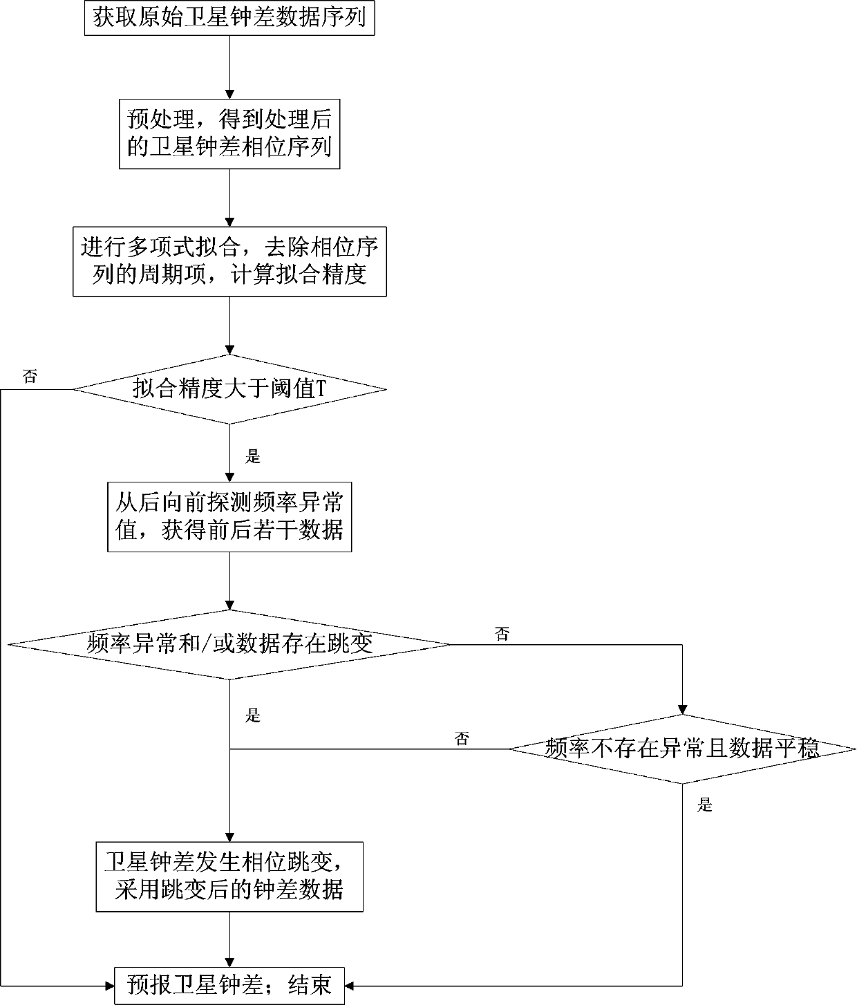
[0026] The invention relates to a method for real-time prediction of satellite clock difference based on phase jump, and the method includes the following steps.

[0027] Step 1: Obtain the original satellite clock data sequence.

[0028] Step 2: Preprocessing the original satellite clock error data sequence to obtain the processed satellite clock erro...


PUM


Abstract

The invention relates to a satellite clock error real-time prediction method based on a phase jump. The satellite clock error real-time prediction method comprises steps of: acquiring an original satellite clock error data sequence, preprocessing the original satellite clock error data sequence, performing polynomial fitting on a processed satellite clock error phase sequence, removing a periodicterm of the phase sequence, and calculating fitting precision; and predicting a satellite clock error and ending the operations if the fitting precision is less than a threshold value, detecting a frequency abnormal values from back to front if the fitting precision is greater than the threshold value to obtain a plurality of pieces of front and back data, predicting a satellite clock error and ending the operations if no anomaly occurs in frequency and the data is stable, and predicting a satellite clock error and ending the operations by adopting clock error data after the jump if the frequency is abnormal and/or the jump exists in the data. The satellite clock error real-time prediction method fully considers the frequency stability and frequency drift features of an atomic clock, performs order selection on GPS, GLONASS, BDS and Galileo, is applied to real-time clock error prediction of a satellite-based augmentation system, is stable and reliable in clock error prediction, improves clock difference error precision in SSR correction information, and improves the precision of the terminal positioning service.

Description

technical field [0001] The invention belongs to the technical field of radio orientation; radio navigation; distance measurement or speed measurement by radio wave; positioning or presence detection by radio wave reflection or re-radiation; Real-time forecasting method of satellite clock error. Background technique [0002] The clock difference is a very important concept in the GPS positioning system, which directly affects the accuracy of the GPS positioning system. When the satellite clock difference cannot be accurately known, it will affect the normal operation of the overall positioning system. [0003] In order to obtain high-precision satellite forecast clock errors, different types of satellite clocks generally use different types of polynomial forecast models. For example, since Rb atomic clocks are mainly used on small time-keeping platforms, and the accuracy requirements are not too high, the frequency drift characteristics of Rb atomic clocks are more obvious t...

Claims


Application Information

Patent Timeline
Patent Type & Authority Applications(China)
IPC IPC(8): G01S19/37
CPCG01S19/37
Inventor 熊超崔红正周培源
Owner QIANXUN SI NETWORK ZHEJIANG CO LTD
Why Eureka
Try Eureka