
Lens structure group for researching actions of physical experimental lens on light

A technology of physical experiment and lens structure, applied in educational appliances, instruments, teaching models, etc., can solve problems such as troublesome operation, poor functionality, and single effect, and achieve the effect of improving practicability, improving functionality, and applying hygiene

Inactive Publication Date: 2018-06-01
新昌县羽林街道星捷轴承厂
View PDF2 Cites 1 Cited by
  • Summary
  • Abstract
  • Description
  • Claims
  • Application Information

AI Technical Summary

Problems solved by technology

[0007] In order to solve the above-mentioned technical problems, the present invention provides a lens structure group for the research of the effect of the physical experiment lens on light, so as to solve the problem that the existing physics lens assembly has a single structure and poor functionality, and the light source results tested in the physics teaching experiment process should be diversified. Obviously, the effect of traditional spotlight projection teaching tools is single, and the performance of extended teaching is poor. In particular, two groups of adjacent lenses cannot be replaced, and the installation structure used between multiple groups of lens frames is too complicated. The traditional candle lighting method is used as the Troublesome problems in the application and operation of light source components

Method used


Image

  • Lens structure group for researching actions of physical experimental lens on light
  • Lens structure group for researching actions of physical experimental lens on light
  • Lens structure group for researching actions of physical experimental lens on light

Examples


Embodiment

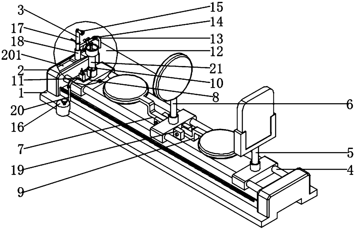
[0031] as attached figure 1 to attach Figure 8 Shown:

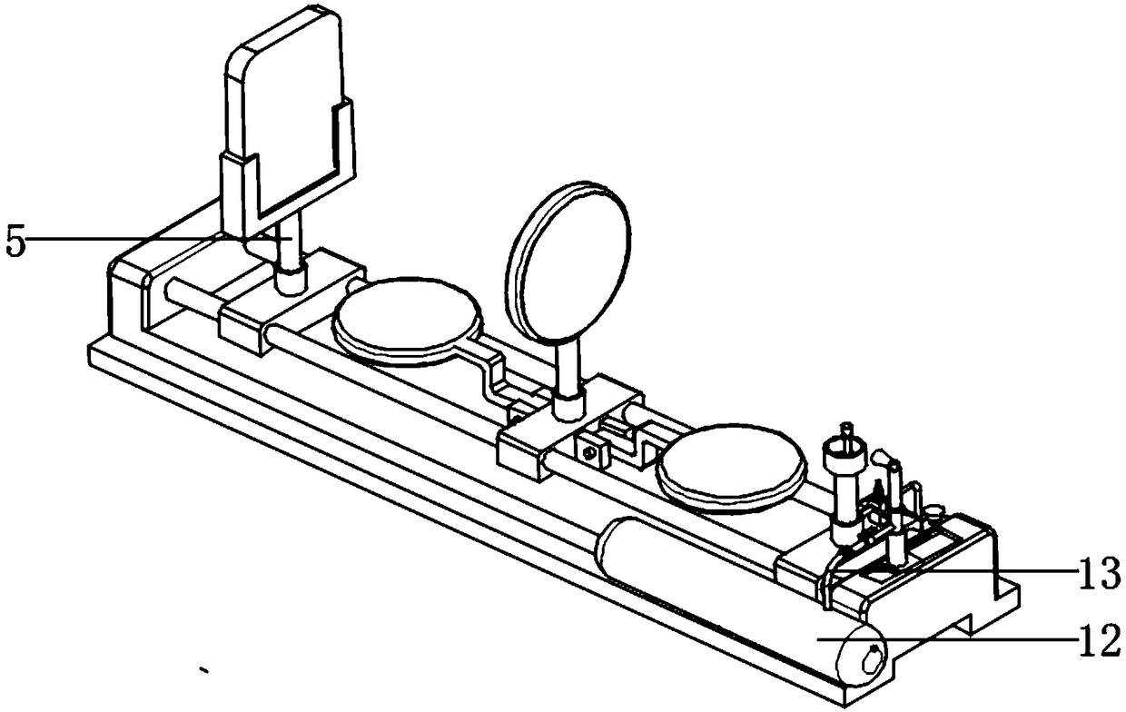
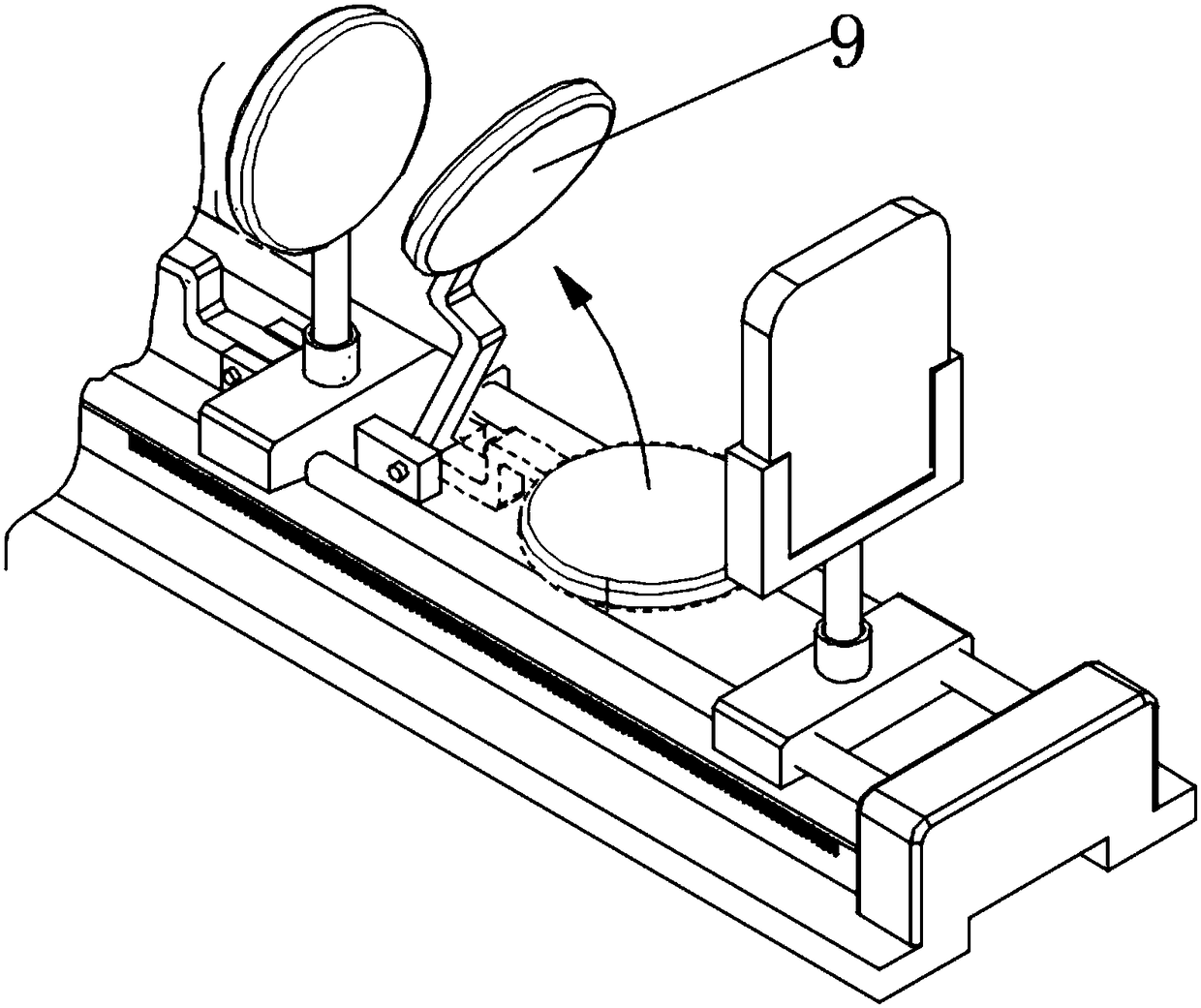
[0032] The invention provides a lens structure group for studying the effect of a physical experiment lens on light, including a base plate 1, left and right columns 2, chute 201, an air blowing seat 3, a sliding tube 4, an image seat 5, a middle lens frame 6, and a left lens frame 7. Lamp holder 8, right lens holder 9, electronic ignition rod 10, electronic ignition frame 11, first gas tank 12, first gas outlet pipe 13, corrugated section 14, gas outlet head 15, second gas tank 16, trigger Rod 17, shaft sleeve 18, slider 1801, connecting lug 19, second air outlet pipe 20, ignition seat 21, connecting sleeve 22, object clamping frame 23 and clip 2301; the top surface of the bottom plate 1 passes through the left and right uprights 2 The way of running through the two sliding tubes 4 is slidingly fitted with an image holder 5, an intermediate lens holder 6 and a lamp holder 8, wherein the left and right end faces of the...


PUM


Abstract

The invention provides a lens structure group for researching actions of a physical experimental lens on light. The lens structure group comprises a left lens frame, a lamp holder, a right lens frame,a first venting pipe and a corrugated section; an imaging base, a middle lens frame and the lamp holder are matched to the top surface of a base plate in a sliding mode in the way that left and rightvertical pillars run through two sliding pipes, wherein the left lens frame is in interference fit to the left end face of the middle lens frame and the right lens frame is in interference fit to theright end face of the middle lens frame in a mode of making connecting lifting lugs get matched with rubber connecting sleeves; the fire point of a light source is slowly blown, so that the fire point gets deflected, and functionality is enhanced; on the basis of the function, the light source is changed, so that light source images in various states are presented on an imaging plate in a teaching experimental process, and practicability is enhanced; and in addition, a detachable object clamping frame is also arranged between a light source piece and a lens, so that simultaneous projection ofobjects and the light source is achieved, viewing effect is enhanced, and the practicability is further improved.

Description

technical field [0001] The invention belongs to the technical field of teaching tool structure and physical experiment equipment, and in particular relates to a lens structure group for studying the effect of physical experiment lenses on light. Background technique [0002] In physics teaching, concave mirrors and convex mirrors both use the principle of light refraction to form images. Optical microscopes and telescopes (including some astronomical telescopes) are made by using the principles of light refraction and linear propagation of light. Magnifiers and microscopes are used for observation and placement. Convex lens for objects that should be magnified near the observer. [0003] For example, the application number: 201621452547.6 relates to a related technical field of a small-hole imaging experimental device, specifically a small-hole imaging experimental device that is easy to use, including a support plate and a movable plate. The inside of the through hole is c...

Claims


Application Information

Patent Timeline
IPC IPC(8): G09B23/22
CPCG09B23/22
Inventor 竺秋君王伟东赖泽江
Owner 新昌县羽林街道星捷轴承厂
Learn More