Power distribution box

A technology for distribution boxes and boxes, which is applied in the substation/distribution device casing, electrical components, magnetic field/electric field shielding, etc., which can solve problems such as failure, difficulty in meeting the leveling requirements of the area, and damage to components, so as to avoid electromagnetic interference , Good effect and safe effect

Inactive Publication Date: 2018-06-01
辽宁东鹰航空装备科技股份有限公司
View PDF0 Cites 3 Cited by
  • Summary
  • Abstract
  • Description
  • Claims
  • Application Information

AI Technical Summary

Problems solved by technology

All the components are in one box. Some of these components are high-voltage components and some are low-voltage components. They are placed in the same box. Electromagnetic interference will occur between high-voltage components and low-voltage components, which will affect the normal operation of the equipment. Use, and even lead to damage and failure of some components, resulting in unsafe and reliable operation of the machine
[0003] When the electrical control box is used in various occasions, due to the electromagnetic interference generated by various electrical equipment with electromagnetic effects on the electrical control box, the electrical control box often cannot work normally.
[0004] The existing electrical control box body and the box door generally adopt plane contact. Since the box body surface in contact with the box door is made of sheet metal, its area is large and it is difficult to meet the flatness requirements. Even if the box body surface or the box door Rubber and other flexible materials are used for sealing, and there is still a certain non-conductive gap between the box body surface and the box door, which cannot form a complete conductive shield between the box door and the box body, so that it is impossible to seal all the inside of the box body. Complete shielding between electrical components and the outside world

Method used


Image

  • Power distribution box
  • Power distribution box

Examples


Embodiment Construction

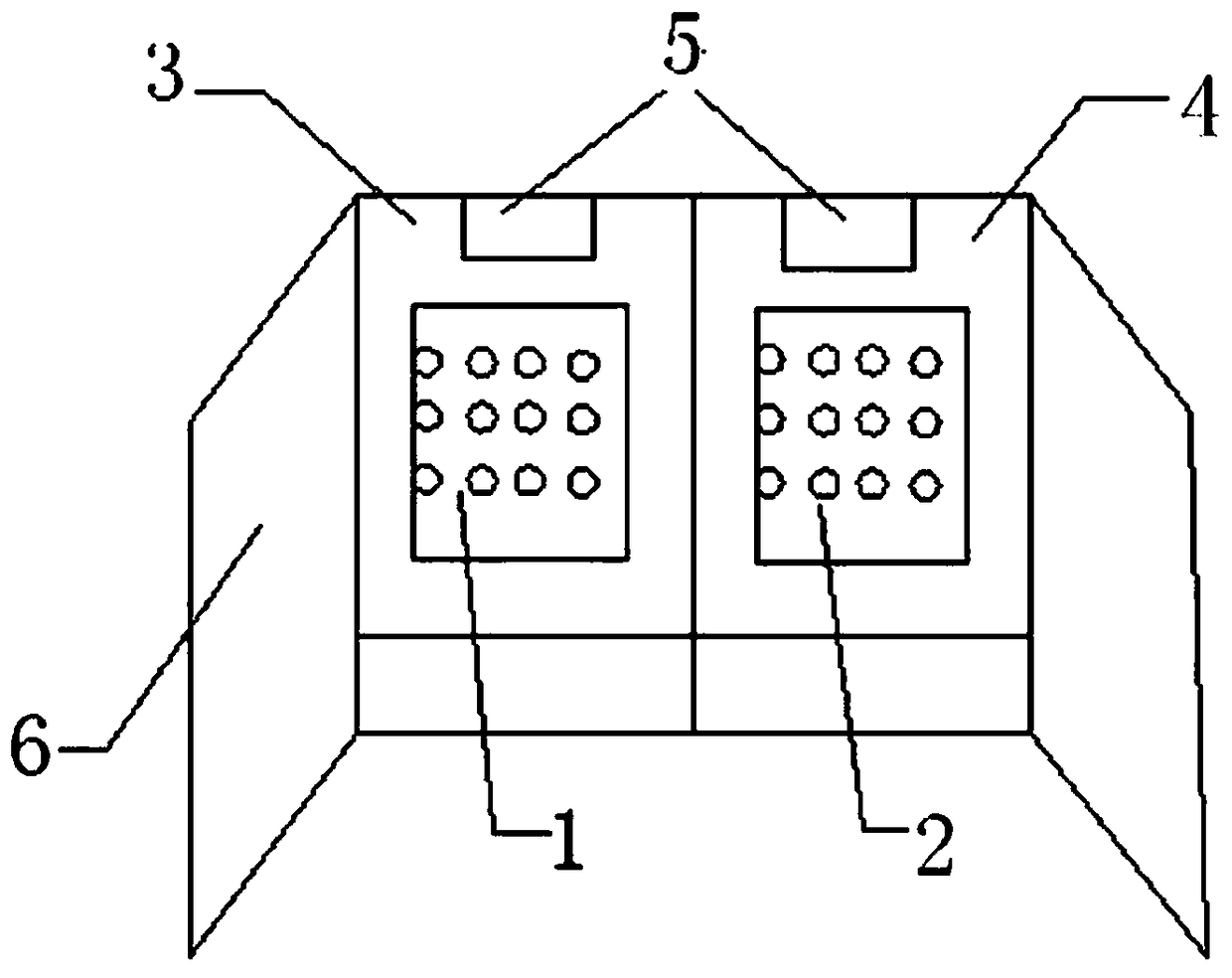
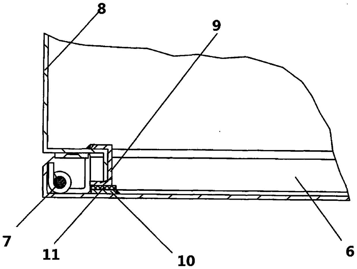
[0018] Such as Figure 1-2 As shown, the present invention includes a box body, a box door 6 and components placed in the box body. It is characterized in that: one side of the box door 6 is hinged with the distribution box body 8 through several door hinges 7. It is characterized in that: The opening of the distribution box 8 is provided with a closed shielding door frame 9, the inner side of the shielding door frame 9 is fixedly connected to the distribution box 8, and an electromagnetic shielding is provided between the outer side and the inner side of the box door 6. Door sealing structure; the electromagnetic shielding door sealing structure includes a sealing frame substrate 10 and a conductive rubber sealing frame 11, the sealing frame substrate 10 is fixedly connected to the inner side of the box door 6, and the conductive rubber sealing frame 11 is bonded and fixed by conductive glue On the sealing frame substrate 10, the position of the conductive rubber sealing fram...


PUM


Abstract

The invention particularly relates to a power distribution box, and belongs to the technical field of electrical control. By virtue of the power distribution box, electromagnetic interference betweenhigh-voltage and low-voltage components can be avoided, and safety and reliability are achieved; meanwhile, the power distribution box provides an electromagnetic shielding function, so that the normal operation requirement of an electric control box can be satisfied; the power distribution box comprises a box body, a box door and components placed in the box body; one side of the box door is hinged with the power distribution box body through several door hinges; a ring of sealed shielding door frame is arranged in the opening of the power distribution box body; the inner side edge of the shielding door frame is fixedly connected with the power distribution box body, and an electromagnetic shielding door sealed structure is arranged between the outer side edge and the inner side surface of the box door; the electromagnetic shielding door sealed structure comprises a sealed frame substrate and a conductive rubber sealed frame; the sealed frame substrate is fixedly connected with the inner side of the box door; the conductive rubber sealed frame is glued and fixed on the sealed frame substrate through conductive adhesive; and the position of the conductive rubber sealed frame is corresponding to the outer side edge position of the shielding door frame.

Description

technical field [0001] The invention belongs to the technical field of electrical control, in particular to a distribution box. Background technique [0002] The electrical control box is a device used to centrally install various contactors, controllers, reactors, switches or other electrical components. Air switches, relays, contactors, circuit breakers, and fuses (fuse) are generally installed in the distribution box. , integrated circuits, sockets and other electrical components, these control components and connection circuits are designed according to the control requirements of specific equipment. All the components are in one box. Some of these components are high-voltage components and some are low-voltage components. They are placed in the same box. Electromagnetic interference will occur between high-voltage components and low-voltage components, which will affect the normal operation of the equipment. Use, and even lead to damage and failure of some components, ...

Claims


Application Information

Patent Timeline
Patent Type & Authority Applications(China)
IPC IPC(8): H02B1/28H05K9/00
CPCH02B1/28H05K9/0016
Inventor 宋文康
Owner 辽宁东鹰航空装备科技股份有限公司
Why Eureka
Try Eureka