Installation structure of rolling door motor and installation method of rolling door motor

A rolling shutter door motor and installation structure technology, applied in the direction of electromechanical devices, electrical components, electric components, etc., can solve the problems of difficult installation of the motor, large force of the feet, and the impact of maintenance costs, so as to achieve convenient and fast installation, improve accuracy, and improve The effect of stability

Pending Publication Date: 2018-06-01
ZHANGZHOU CHANGTAI NEW QILIN MACHINE
View PDF0 Cites 1 Cited by
  • Summary
  • Abstract
  • Description
  • Claims
  • Application Information

AI Technical Summary

Problems solved by technology

This installation method has two main problems: 1. Due to the installation direction and self-weight of the motor, it is difficult to install the motor, and it is necessary to stabilize the motor at all times during the process; 2. When the motor drives the rolling door to rotate, the force on the feet is relatively large , the problem of motor foot damage is one of the most important factors affecting the life of the motor, which also has a great impact on the maintenance cost in the later period

Method used


Image

  • Installation structure of rolling door motor and installation method of rolling door motor
  • Installation structure of rolling door motor and installation method of rolling door motor
  • Installation structure of rolling door motor and installation method of rolling door motor

Examples


Embodiment 1

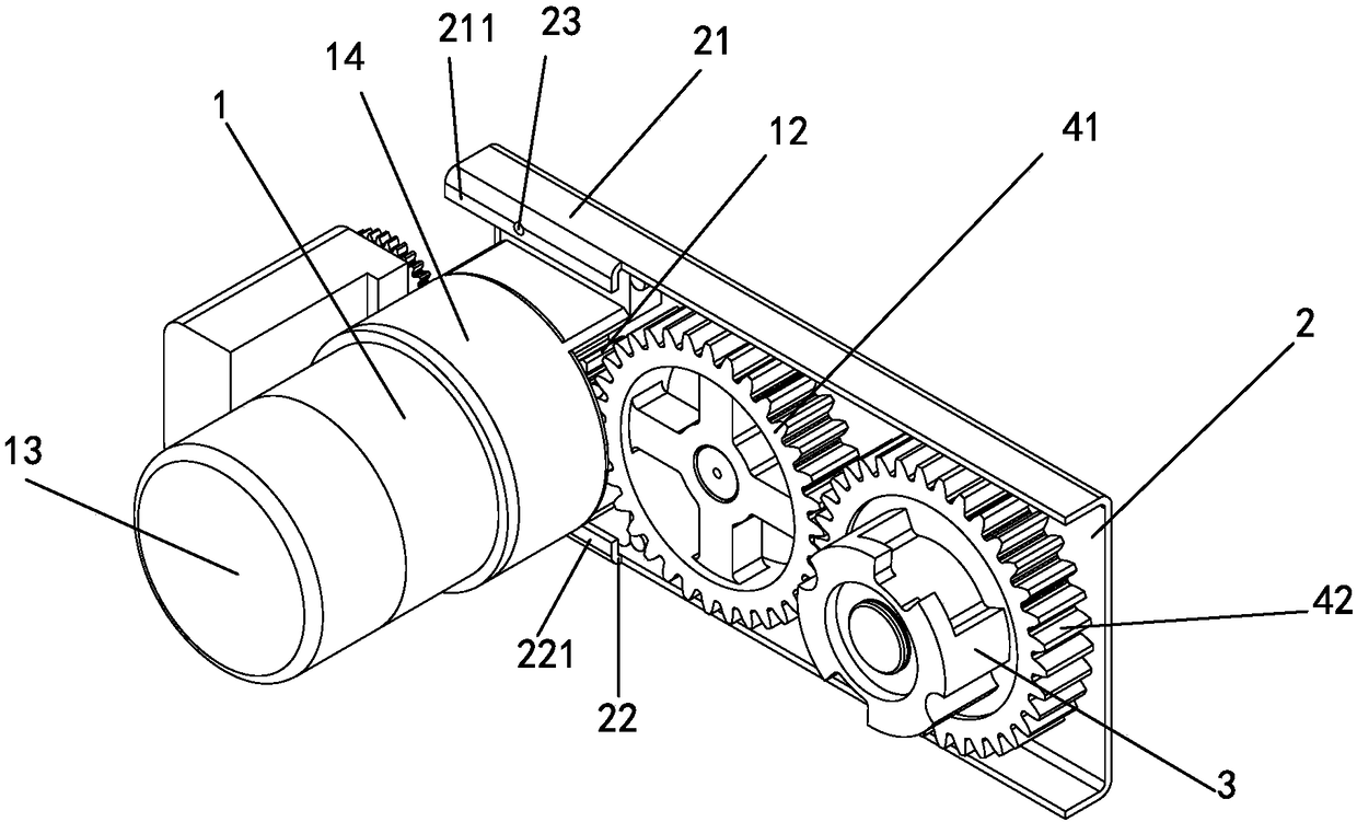
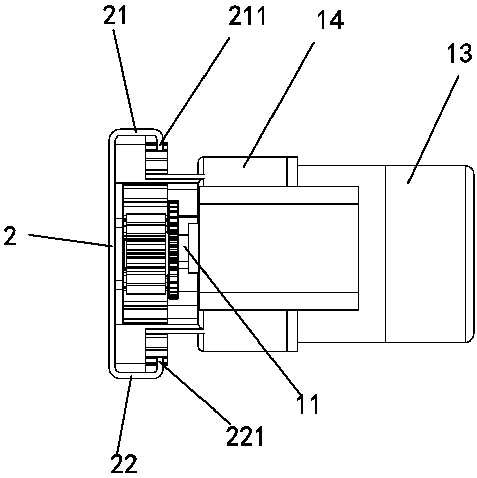
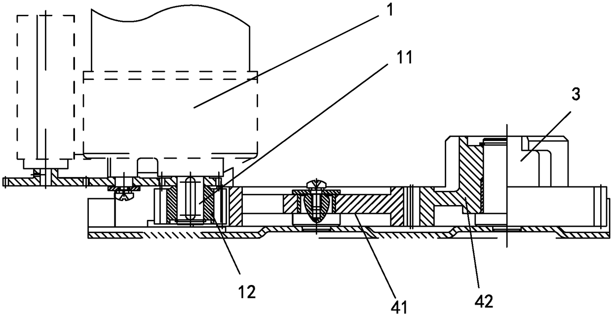
[0037] Embodiment one, see Figure 1 to Figure 3 As shown, the mounting structure of a rolling door motor of the present invention includes a motor 1, a mounting plate 2 and a reel gear 3, and the motor 1 and the reel gear 3 are respectively installed on the mounting plate 2, from the installation direction , the motor 1 and the reel gear 3 are installed on the left and right sides of the mounting plate 2 respectively. In this embodiment, the motor 1 refers to the motor assembly, which includes a driving motor 13 and a reduction box 14. The output shaft of the reduction box 14, that is, the output shaft 11 of the motor 1, is connected to the reel gear 3 through a transmission mechanism to drive the rolling door up and down. movable; the mounting plate 2 is provided with an upper positioning block 21 and a lower positioning block 22 corresponding to the position of the motor 1, and the bottom of the motor 1 is positioned and mounted on the mounting plate 2 through the upper and...

Embodiment 2

[0042] Embodiment two, see Figure 4As shown, the difference between this embodiment and Embodiment 1 is that: the upper positioning block 21 and the lower positioning block 22 are respectively a right-angled structure; one side of the right-angled part is perpendicular to the mounting plate 2 to form the upper and lower parts of the motor respectively. The other side of the positioning surface is parallel to the mounting plate 2 to form upper and lower limiting surfaces to prevent the motor from coming out, and the two right-angle parts are oppositely arranged; the motor 1 is installed in the slot formed by the two right-angle parts. The opposite sides of the upper and lower positioning blocks are parallel to each other. In addition to the shape of the right-angled piece, other connecting pieces that are not in a right-angled relationship are also applicable, as long as they can form the upper and lower positioning surfaces of the motor and the upper and lower limiting surfac...

Embodiment 3

[0043] Embodiment three, see Figure 5 As shown, the difference between the present embodiment and the second embodiment is that the opposite sides of the upper and lower positioning blocks 21 and 22 gradually approach along the traveling direction of the motor 1 . The mounting plate 2 is provided with a limiting member 24 of the motor 1 for accurate positioning and installation of the motor 1 .


PUM


Abstract

The invention discloses an installation structure of a rolling door motor. The installation structure comprises a motor, an installation plate and a rolling shaft gear, wherein the motor and the rolling shaft gear are arranged on the installation plate, an output shaft of the motor is connected with the rolling shaft gear by a transmission mechanism so as to drive a rolling door to move upwards and downwards, an upper positioning block and a lower positioning block are arranged at a position, corresponding to the motor, of the installation plate, the bottom of the motor is positioned and arranged on the installation plate by the upper positioning block and the lower positioning block, and the bottom of the motor is pushed to be connected between the upper positioning block and the lower positioning block from a side surface of the installation plate. Different from the prior art, the installation structure of the rolling door motor has the advantages that a fixing mode of a leg and a stud in the prior art is changed to a fixing mode that the bottom of the motor is inserted from the side surface of the installation plate, under the effects of the upper positioning block and the lower positioning block, the motor can be fixed on the installation plate by a bolt after being pushed from the side surface, and the installation structure has the advantage of novel structure and is rapid and convenient to install.

Description

technical field [0001] The invention relates to an installation structure of a rolling door motor and an installation method of the rolling door motor. Background technique [0002] The installation method of the traditional rolling door motor is as follows: the mounting plate is installed with the mounting studs of the reel gear and the motor. Gear drive connection. This installation method has two main problems: 1. Due to the installation direction and self-weight of the motor, it is difficult to install the motor, and it is necessary to stabilize the motor at all times during the process; 2. When the motor drives the rolling door to rotate, the force on the feet is relatively large , The problem of damage to the legs of the motor is one of the more important factors affecting the life of the motor, which also has a great impact on the later maintenance costs. Contents of the invention [0003] The purpose of the present invention is to overcome the deficiencies of the...

Claims


Application Information

Patent Timeline
Patent Type & Authority Applications(China)
IPC IPC(8): H02K7/116H02K7/10H02K5/00
CPCH02K7/116H02K5/00H02K7/10
Inventor 陈菁
Owner ZHANGZHOU CHANGTAI NEW QILIN MACHINE
Why Eureka
Try Eureka