
Reference signal transmission method and device

A reference signal and transmission method technology, which is applied in the field of reference signal transmission method and device, and can solve the problems of high probability of misselection of precoding vectors, etc.

Active Publication Date: 2018-06-01
ZTE CORP
View PDF10 Cites 12 Cited by
  • Summary
  • Abstract
  • Description
  • Claims
  • Application Information

AI Technical Summary

Problems solved by technology

[0013] Embodiments of the present invention provide a reference signal transmission method and device, a base station, and a terminal, so as to at least solve the problem in the related art that the probability of misselection of the precoding vector caused by the CSI-RS measurement error is high

Method used


Image

  • Reference signal transmission method and device

Examples


Embodiment 1

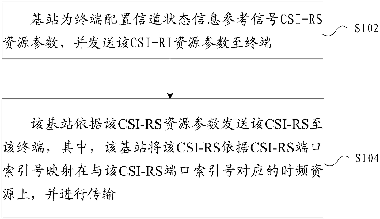
[0071] In this embodiment, a method for transmitting a reference signal operating on the above-mentioned base station is provided, figure 1 is a flowchart of a reference signal transmission method according to an embodiment of the present invention, such as figure 1 As shown, the process includes the following steps:

[0072] Step S102, the base station configures channel state information reference signal CSI-RS resource parameters for the terminal, and sends the CSI-RI resource parameters to the terminal;

[0073] Step S104, the base station sends the CSI-RS to the terminal according to the CSI-RS resource parameter, wherein the base station maps the CSI-RS to the time corresponding to the CSI-RS port index number according to the CSI-RS port index number on the frequency resource and transmit it.

[0074] Through the above steps, the base station configures channel state information reference signal CSI-RS resource parameters for the terminal, and sends the CSI-RI resourc...

Embodiment 1-2

[0141] Optional embodiment 1-2: CSI-RS is transmitted on time-frequency resources according to the port index number mapping, the port index number of CSI-RS is determined by the CDM RE Group index number, and the CDM RE Group index number is determined according to the frequency domain frequency

[0142] For example: the CDM Group with high frequency has a small index number, and the CDM Group with low frequency has a large index number;

[0143] For example, the CDM Group with high frequency has a high index number, and the CDM Group with low frequency has a small index number.

Embodiment 1-2-1

[0144] Optional embodiment 1-2-1: CDM RE Group index numbers are determined according to the frequency in the frequency domain, and determined in sequence in the time domain;

[0145] For example: the index number of the CDM Group with high frequency is small, the index number of CDM Group with low frequency is large, the index number of the CDM Group earlier in the time domain is small, and the index number of the CDM Group later in the time domain is large;

[0146] For example, the CDM Group with high frequency has a high index number, and the CDM Group with low frequency has a small index number; the CDM Group with the earliest time domain has a small index number, and the CDM Group with a later time domain has a large index number.


PUM


Abstract

The invention provides a reference signal transmission method and device. The method comprises the following steps that a base station configures channel-state information reference signal (CSI-RS) resource parameters for a terminal and sends the channel-state information reference signal resource parameters to the terminal; and the base station sends a CSI-RS to the terminal according to the CSI-RS resource parameters, wherein the base station maps the CSI-RS to a time-frequency resource corresponding to a CSI-RS port index number according to the CSI-RS port index number and carries out transmission. By the adoption of the technical scheme, a problem of large false selection probability of a precoding vector, which is caused by a CSI-RS measurement error in the correlation technique is solved, the terminal is guaranteed to carry out detection on the CSI-RS according to the resource parameters issued by the base station, the transmission stability is improved, and the false selectionprobability is greatly reduced.

Description

technical field [0001] The present invention relates to the communication field, in particular, to a method and device for transmitting a reference signal. Background technique [0002] In related technologies, with the rapid development of wireless communication requirements in life and production, the fourth generation of long-term evolution technology (Long Term Evolution, referred to as LTE), long-term evolution upgrade technology (LTE-A, LTE-Advanced), and The fifth-generation new radio access technology (NR, New RAT, New Radio Access Technology) schemes all use technologies based on Orthogonal Frequency Division Multiplexing (OFDM, Orthogonal Frequency Division Multiplexing) modulation. In a communication system based on OFDM technology, OFDM symbols are the smallest unit of transmission signals in the time domain, and multiple OFDM symbols form a time slot (Slot), with Slot as the smallest scheduling unit in the time domain; multiple Slots form a frame (Frame), as th...

Claims


Application Information

Patent Timeline
IPC IPC(8): H04L5/00H04L27/26H04L1/06H04B7/06H04B7/0456
CPCH04L5/0048H04L5/0007
Inventor 李永鲁照华蒋创新陈艺戬李儒岳
Owner ZTE CORP
Learn More