Mover opening/closing control device

A technology of closing control and moving body, applied in the directions of transportation and packaging, power control mechanism, wing fan control mechanism, etc., can solve problems such as difficulty in manual opening, and achieve the effect of ensuring detection

Inactive Publication Date: 2006-07-12
PANASONIC CORP
View PDF4 Cites 11 Cited by
  • Summary
  • Abstract
  • Description
  • Claims
  • Application Information

AI Technical Summary

Problems solved by technology

In addition, the increasing phenomenon of female drivers driving such as large passenger cars is also a cause of this trend. door and back door feel

Method used


Image

  • Mover opening/closing control device
  • Mover opening/closing control device
  • Mover opening/closing control device

Examples


Embodiment 1

[0063] Figure 1~6 A movable body opening and closing device according to Embodiment 1 of the present invention and an application example thereof are shown.

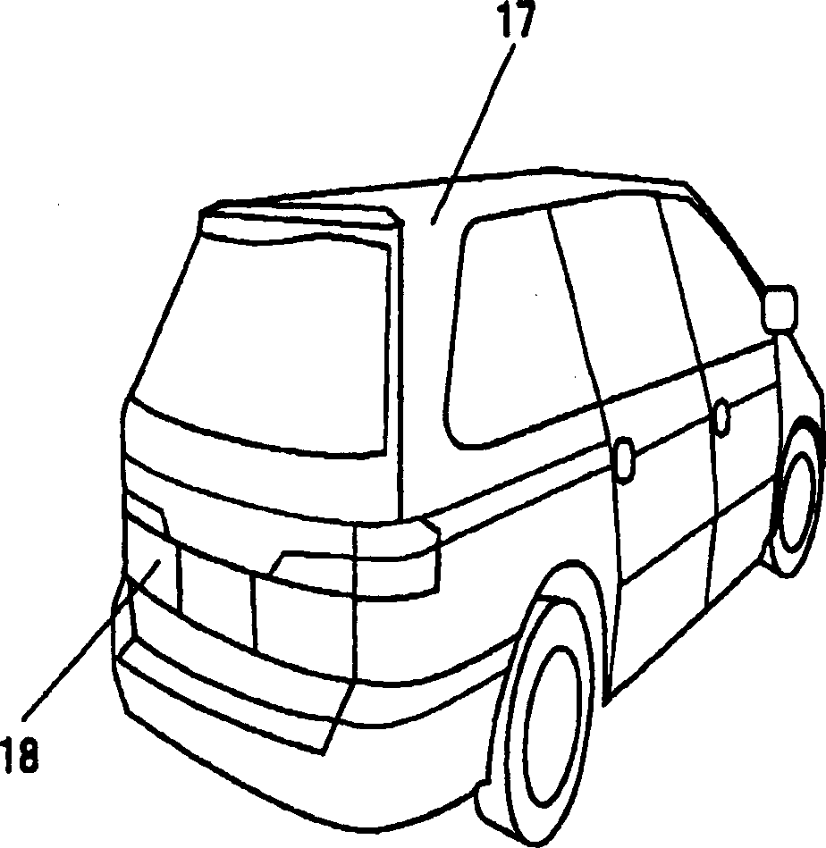
[0064] figure 1 It is a perspective view of a vehicle on which the device of the present invention is mounted as a movable body on a rear door. The rear door 18 is mounted on the rear portion of the vehicle body 17 in a manner that can be freely opened and closed.

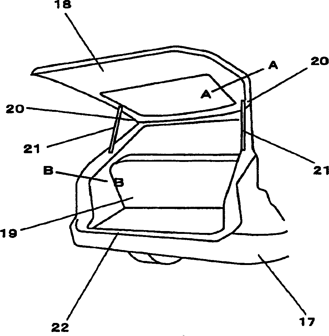
[0065] figure 2 is a perspective view showing a state in which the rear door 18 is opened. When the rear door 18 is opened, a luggage space (luggage compartment) 19 is formed so that luggage and the like can be loaded and unloaded from the inside of the vehicle. The rear door 18 is rotatably supported by a hinge 20 (not shown) near an upper end, and rotated by a rear door motor (not shown). The rear door 18 is supported by shock absorbers 21 . Each shock absorber 21 is composed of a cylinder and a piston for absorbing a shock caused when the rear doo...

Embodiment 2

[0090] Figure 9 The movable body opening and closing device according to Embodiment 2 of the present invention is shown, and since the basic structure and function of Embodiment 2 are the same as those of Embodiment 1, only the differences from Embodiment 1 will be described below.

[0091] The difference between embodiment 2 and embodiment 1 is that the sensor is arranged along the figure 2 In the cross-section made by the line B-B. In other words, the sensor is not provided on the side of the movable body, but on the vehicle body constituting the fixed side.

[0092] In this structure, since the sensor is provided on the fixed side, the sensor is hardly affected by the vibration generated by the door when the door is opened and closed, so that stable detection can be expected.

Embodiment 3

[0094] Figure 10 A movable body opening and closing device according to Embodiment 3 of the present invention is shown. Since the basic structure and function of Embodiment 3 are the same as those of Embodiment 1, only the differences from Embodiment 1 will be described below.

[0095] As shown in the figure, the piezoelectric sensor may be provided on a cross section at one end of the sliding door 43 taken along the line A-A. In addition, the present invention can be similarly applied to the cross-section of the sunroof 44 taken along the line B-B. Moreover, the present invention can also be provided on the cross-section of the power window 45 made along the line C-C.

[0096] Among these structures, the invention can be widely applied not only to rear doors, but also to sliding doors, sunroofs, and power windows.


PUM


Abstract

An object of the invention is to safely execute a sudden door opening operation in course of door opening, in a mover opening/closing control device. To solve the above problem, the mover opening/closing control device of the invention comprises an openable/closable mover for a main body, a drive means (4) for driving the mover, an input means (1) for commanding the mover to open/close, a flexible cable-like piezoelectric sensor (29) for detecting trapping caused by the mover, and a control section (35) for controlling them, wherein the operation is controlled such that when a door closing command is issued from the input means (1) in course of door opening, the door closing operation is delayed until the mover reaches a predetermined door opening position, whereby it becomes possible for the operator to visually confirm the outside of the mover in response to the sudden door closing command in course of door opening, so that the danger of trapping in the mover can be prevented.

Description

technical field [0001] The present invention relates to an opening and closing control device for movable bodies of self-starting equipment, automatic electric windows, electric sliding doors and electric sunshade roofs, automatic doors of buildings and the like. More specifically, it relates to opening and closing control of a movable body when a closing instruction is received while the movable body is opened. Background technique [0002] In recent years, devices that automatically open and close a moving body by a driving source such as a motor are increasing. As this type of equipment and systems, elevator doors and automatic entry and exit doors of buildings are known. In motor vehicles, a mode in which a heavy sliding door and a rear door are opened and closed by an electric motor bias by manipulating a switch without any manual operation is increasing. At present, the trend of diversification and diversification of users' hobbies from cars is increasing, and the fo...

Claims


Application Information

Patent Timeline
Patent Type & Authority Applications(China)
IPC IPC(8): E05F15/10B60J1/00B60J5/00B60J5/06B60J5/10B60J7/057
Inventor 植田茂树荻野弘之
Owner PANASONIC CORP
Why Eureka
Try Eureka