
Fixing structure of graphene electrothermal film

A fixed structure, electric heating film technology, applied in the field of graphene, can solve the problems of graphene electric heating film damage, etc., to achieve the effect of fast heating, convenient power on, and convenient replacement

Active Publication Date: 2018-06-01
NINGBO COLLEGE OF HEALTH SCI
View PDF1 Cites 0 Cited by
  • Summary
  • Abstract
  • Description
  • Claims
  • Application Information

AI Technical Summary

Problems solved by technology

[0004] However, the graphene electric heating film is generally flexible and transparent, but when the graphene electric heating film is used for heating, the graphene electric heating film is easily damaged, so the graphene electric heating film needs to be protected

Method used


Image

  • Fixing structure of graphene electrothermal film
  • Fixing structure of graphene electrothermal film
  • Fixing structure of graphene electrothermal film

Examples


Embodiment 1

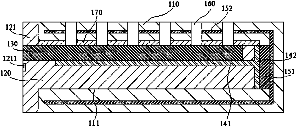
[0073] Such as figure 1 As shown, the present embodiment provides a graphene-based heating device, including a protective layer 110, the protective layer 110 is provided with an installation cavity 111 with an opening to the left, and a support plate 120 is inserted in the installation cavity 111, and the support plate 120 is left A baffle 121 is provided on the side, and the baffle 121 is located on the left side of the installation cavity 111 and the baffle 121 is attached to the left side of the protective layer 110 .

[0074] The support plate 120 is inserted into the installation cavity 111 of the protective layer 110, so that the protective layer 111 can effectively protect the support plate 120. The baffle 121 is located on the left side of the support plate 120 and connected in one piece. The baffle 121 plays a role The position limiting function can also facilitate the insertion or withdrawal of the support plate 120 into or out of the installation cavity 111 .

[00...

Embodiment 2

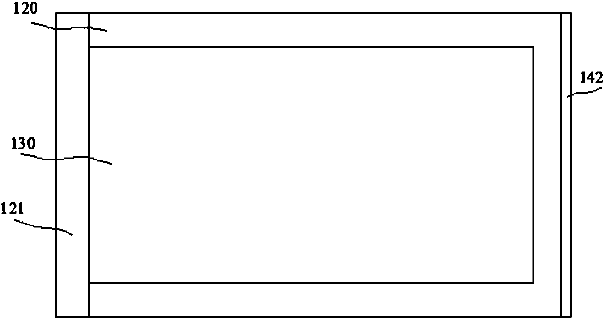
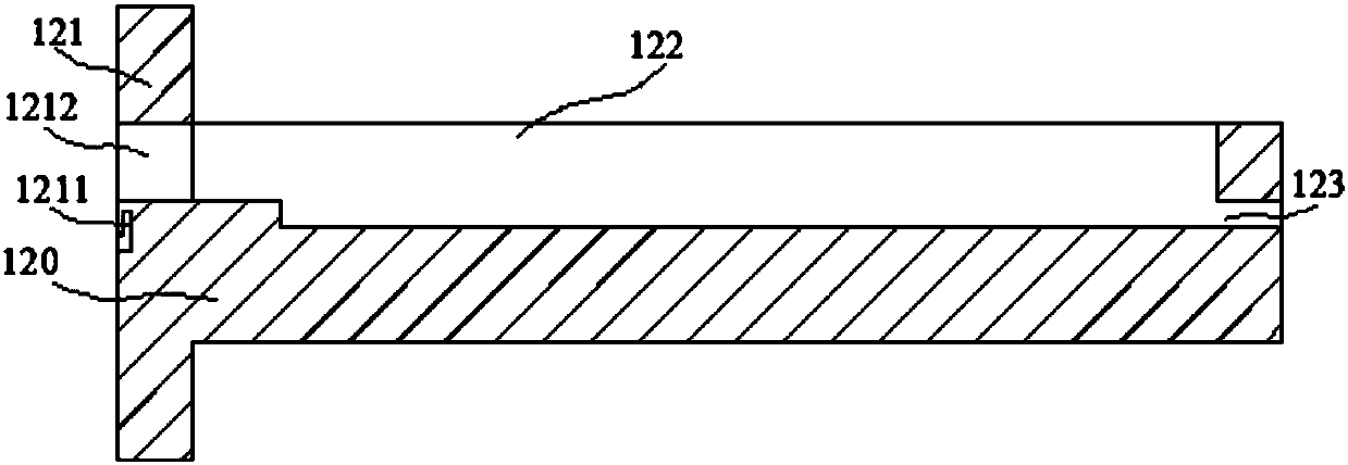
[0091] Such as Figure 5 , Figure 6 and Figure 7 As shown, the present embodiment provides a fixed structure of a graphene electrothermal film, including a protective layer 110, the protective layer 110 is provided with an installation cavity 111 with an opening to the left, and a support plate 120 is inserted in the installation cavity 111, and the support plate 120 A baffle 121 is provided on the left side, and the baffle 121 is located on the left side of the installation cavity 111 and the baffle 121 is attached to the left side of the protective layer 110 .

[0092] The support plate 120 is inserted into the installation cavity 111 of the protective layer 110, so that the protective layer 111 can effectively protect the support plate 120. The baffle 121 is located on the left side of the support plate 120 and connected in one piece. The baffle 121 plays a role The position limiting function can also facilitate the insertion or withdrawal of the support plate 120 into ...

Embodiment 3

[0109] Such as Figure 8 As shown, this embodiment provides a heating device using graphene to generate heat, including a protective layer 110, an installation cavity 111 with an opening to the left is provided in the protection layer 110, a support plate 120 is inserted in the installation cavity 111, and the support plate 120 A baffle 121 is provided on the left side, and the baffle 121 is located on the left side of the installation cavity 111 and the baffle 121 is attached to the left side of the protective layer 110 .

[0110] The support plate 120 is inserted into the installation cavity 111 of the protective layer 110, so that the protective layer 111 can effectively protect the support plate 120. The baffle 121 is located on the left side of the support plate 120 and connected in one piece. The baffle 121 plays a role The position limiting function can also facilitate the insertion or withdrawal of the support plate 120 into or out of the installation cavity 111 .

[...


PUM


Abstract

The invention relates to the technical field of graphene, and relates to a fixing structure of a graphene electrothermal film. An installation cavity with a leftward opening is formed in a protectionlayer of the fixing structure, a supporting plate is plugged in the installation cavity, a baffle is arranged on the left side of the supporting plate, and the baffle is located on the left side of the installation cavity. A first containing cavity is formed in the supporting plate, and the graphene electrothermal film is positioned in the first containing cavity. Convex strips are arranged on theleft side and the right side of the graphene electrothermal film respectively, a blocking strip is arranged at the cavity opening of the first containing cavity, and the blocking strip is used for blocking the convex strips, so that the graphene electrothermal film is fixed in the first containing cavity. Two first electrifying contacts are arranged on the left side surface of the convex strip positioned on the left side of the graphene electrothermal film, the first containing cavity is provided with two second through electrifying contacts which are matched with the two first electrifying contacts, any second electrifying contact is connected with a metal electrifying rod, and the metal electrifying rod penetrates through the supporting plate and the baffle in sequence and then is in threaded connection with the two fastening nuts. The fixing structure can be heated based on graphene, the graphene can be protected, and the heat source is not easy to lose.

Description

technical field [0001] The invention relates to the technical field of graphene, in particular to a fixed structure of a graphene electrothermal film. Background technique [0002] Graphene is a carbon atom with sp 2 The honeycomb planar film formed by hybridization is a quasi-two-dimensional material with only one atomic layer thickness, so it is also called single atomic layer graphite. Graphene has very good strength, flexibility, electrical conductivity, thermal conductivity, and optical properties, and has been greatly developed in the fields of physics, materials science, electronic information, computers, and aerospace. Graphene has very good thermal conductivity properties. The thermal conductivity of pure defect-free single-layer graphene is as high as 5300W / mK, which is the carbon material with the highest thermal conductivity so far, higher than single-walled carbon nanotubes (3500W / mK) and multi-walled carbon nanotubes (3000W / mK) . When it is used as a carrie...

Claims


Application Information

Patent Timeline
IPC IPC(8): H05B3/02H05B3/14H05B3/20H05B3/08
CPCH05B3/02H05B3/08H05B3/145H05B3/20
Inventor 马少华卢金秦志伟凌庆枝
Owner NINGBO COLLEGE OF HEALTH SCI
Learn More