Method for improving strip steel tail part coiling quality

A strip and quality technology, applied in the field of improving the coil quality of the strip tail, can solve the problems of edge loss, reducing the speed of the roller table 3, and poor effect.

Active Publication Date: 2018-06-05
BAOSHAN IRON & STEEL CO LTD
View PDF5 Cites 4 Cited by
  • Summary
  • Abstract
  • Description
  • Claims
  • Application Information

AI Technical Summary

Problems solved by technology

When the loose strip steel is coiled, it is easy to produce overflow edge, fold edge and edge damage defects
[0009] The existing technology adopts the method of roller table lag to solve this problem: when the tail of the strip is thrown out by the last stand 21 of the finishing mill, the speed of the roller table 3 is reduced to make it lower than the running speed of the strip
[0011] 1) The effect is poor when coiling thin strip steel (such as strip steel with a thickness less than or equal to 4mm): reduce the speed of the roller table to make it lower than the operating speed of the strip steel, and the effect is better when coiling thick strip steel, but Thin strip steel has light weight, the friction force between the lower surface of the strip steel and the roller table is small, the tail of the strip steel cannot be tightened, it is still in a loose and unstable state, and quality defects cannot be avoided
[0012] 2) Affect the quality of the lower surface of the strip: the speed of the roller table is lower than the speed of the strip, and there is inevitably friction between the lower surface of the strip and the roller surface, which affects the surface quality
In order to tension the thin strip, the speed difference between the roller table and the strip must be increased, but this increases the possibility of causing surface defects

Method used


Image

  • Method for improving strip steel tail part coiling quality
  • Method for improving strip steel tail part coiling quality
  • Method for improving strip steel tail part coiling quality

Examples


Embodiment Construction

[0032] The method for improving the coiling quality of the steel strip tail of the present invention will be described in further detail below with reference to the accompanying drawings and specific embodiments, but it is not intended to limit the present invention.

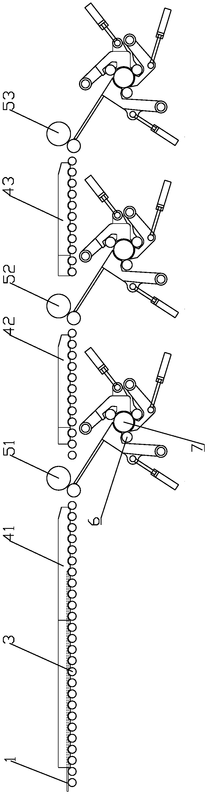
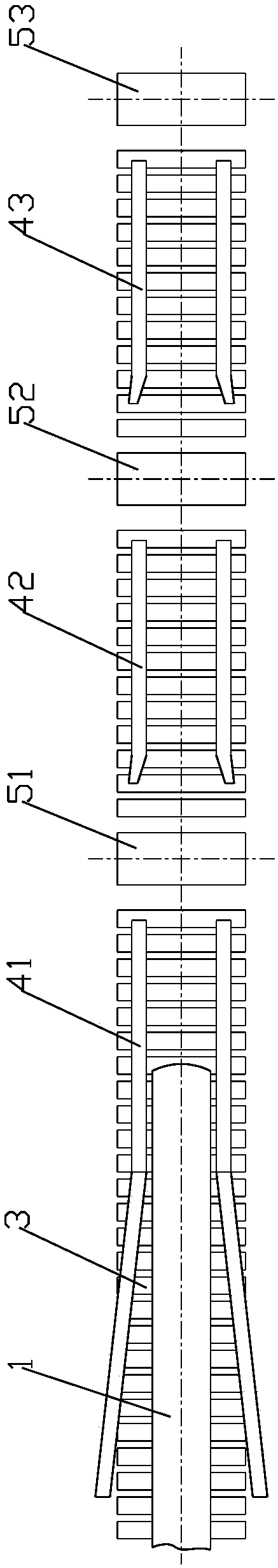
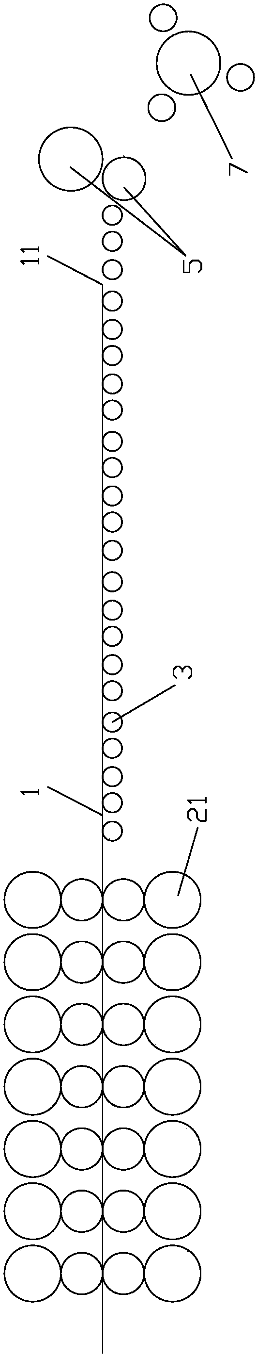
[0033] For the convenience of description, the coilers included in the coiling equipment after the hot rolling mill are sequentially referred to as the first coiler, the second coiler and the third coiler along the running direction of the strip, which will be arranged in the first coiler. The pairs of side guides on both sides of the row of rollers used for positioning the strip before the first coiler, the second coiler and the third coiler are called the first side guide, the first side guide, and the first side guide along the running direction of the strip. Second side guide and third side guide.

[0034] like Figure 11 and Figure 8As shown, the method for improving the coiling quality of the strip tail...


PUM

PropertyMeasurementUnit
thicknessaaaaaaaaaa

Abstract

The invention provides a method for improving strip steel tail part coiling quality. The method is based on coiling equipment arranged behind a hot rolling unit, and the coiling equipment comprises afirst coiling machine and a second coiling machine which are arranged in sequence along the running direction of strip steel, and further comprises a pair of first side guide plates and a pair of second side guide plates. The method comprises the steps that during coiling of the strip steel by the second coiling machine, when the head part of the strip steel reaches an inlet of a pinch roller of the second coiling machine, the pair of second side guide plates are folded to clamp the strip steel; and before the tail part of the strip steel is transported out of a tail frame of a finish rollingunit, the pair of first side guide plates are folded to clamp the strip steel. According to the method for improving the strip steel tail part coiling quality, the side guide plates of the upstream coiling machines are used for clamping the strip steel, and two or more side guide plates are adopted to clamp the strip steel at the same time, so that the friction force between the side guide platesand the edge of the strip steel are improved, the tail part of the strip steel is ensured to be tightened, and the coiling quality of the tail part of the strip steel is improved.

Description

technical field [0001] The invention relates to a method for improving the coiling quality of a strip steel tail in a hot rolling process. Background technique [0002] Coiler is an important equipment of hot rolling production line, which is used to coil hot rolled strip into steel coil. The coiler is located after the finishing mill and is the last process of the hot tandem rolling production line. see figure 1 and 2 , the strip steel 1 is transported from the finishing mill unit to the coiler unit by the roller table 3, and then enters the pinch roller 51 through the centering of the side guide plate 41. The main function of the pinch roller is to apply a certain clamping force to the strip at the head bite stage, and at the same time to perform the first bending deformation; to apply a stable tension to the strip at the tail coiling stage to ensure good Roll quality. Three roll-up rolls 6 help to bend the strip and wrap the strip tightly on the reel 7 . After the r...

Claims


Application Information

Patent Timeline
Patent Type & Authority Applications(China)
IPC IPC(8): B21C47/02B21C47/34
Inventor 幸利军
Owner BAOSHAN IRON & STEEL CO LTD
Why Eureka
Try Eureka