Concrete stirring equipment for road construction

A technology for mixing equipment and road construction, which is applied in the direction of clay preparation equipment, cement mixing equipment, mixing operation control, etc., and can solve problems such as easy splashing of concrete, poor mixing effect, waste, etc.

Inactive Publication Date: 2018-06-05
汤国忠
View PDF5 Cites 9 Cited by
  • Summary
  • Abstract
  • Description
  • Claims
  • Application Information

AI Technical Summary

Problems solved by technology

[0005] In order to overcome the shortcomings of time-consuming and labor-intensive mixing, poor mixing effect and waste caused by concrete splashing during the mixing process, the technical problem to be solved by the invention is to provide a time-saving and labor-saving , The mixing effect is good, the concrete is not easy to splash during the mixing process, and the concrete will not be wasted. Concrete mixing equipment for road construction

Method used


Image

  • Concrete stirring equipment for road construction
  • Concrete stirring equipment for road construction
  • Concrete stirring equipment for road construction

Examples


Embodiment 1

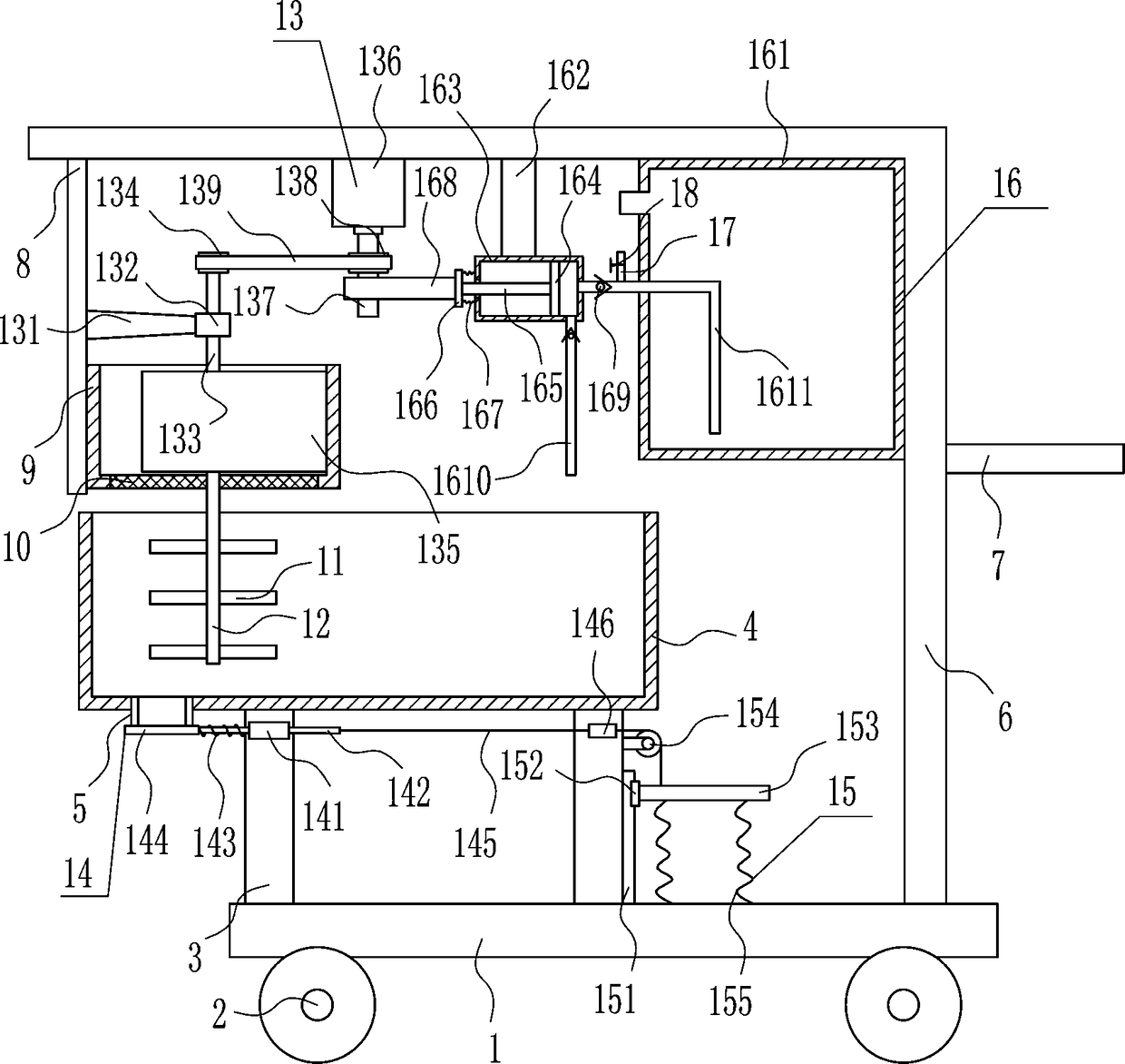
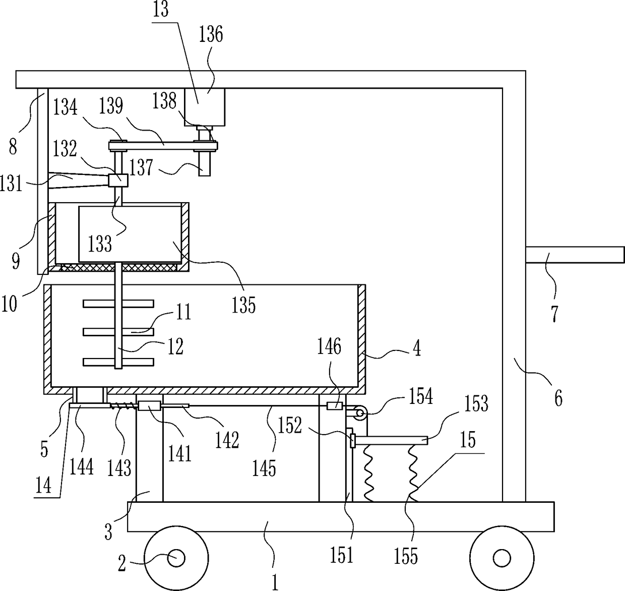
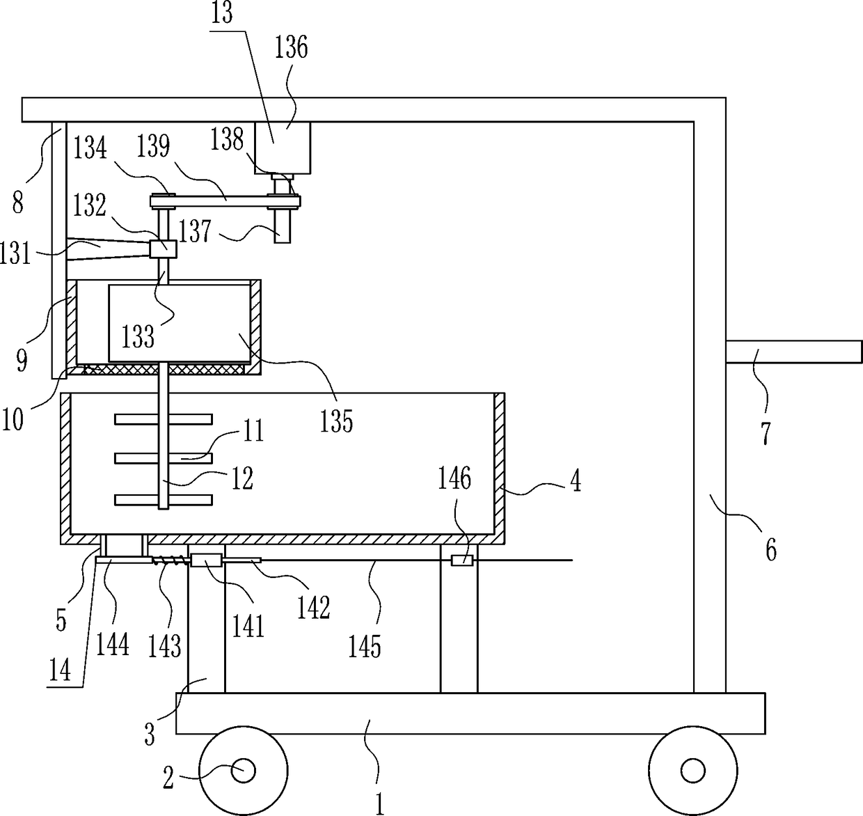
[0031] A concrete mixing plant for road construction, such as Figure 1-5 As shown, it includes bottom plate 1, wheel 2, support rod 3, cylinder body 4, discharge pipe 5, 7-shaped plate 6, push handle 7, vertical plate 8, circular frame 9, mesh plate 10, stirring rod 11, rotary Rod 12, crushing device 13 and feeding mechanism 14, wheels 2 are installed symmetrically on the left and right sides of the bottom of the bottom plate 1, support rods 3 are installed on the left and middle of the top of the bottom plate 1, and between the tops of the support rods 3 on the left and right sides A cylinder 4 is installed, and the left side of the bottom of the cylinder 4 is connected with a discharge pipe 5. The discharge pipe 5 communicates with the inside of the cylinder 4, and the upper part of the front side of the left and right support rods 3 is provided with a feeding mechanism 14. The blanking part of the bottom plate 1 is in contact with the discharge pipe 5, a 7-type plate 6 is ...

Embodiment 2

[0033] A concrete mixing plant for road construction, such as Figure 1-5 As shown, it includes bottom plate 1, wheel 2, support rod 3, cylinder body 4, discharge pipe 5, 7-shaped plate 6, push handle 7, vertical plate 8, circular frame 9, mesh plate 10, stirring rod 11, rotary Rod 12, crushing device 13 and feeding mechanism 14, wheels 2 are installed symmetrically on the left and right sides of the bottom of the bottom plate 1, support rods 3 are installed on the left and middle of the top of the bottom plate 1, and between the tops of the support rods 3 on the left and right sides A cylinder 4 is installed, and the left side of the bottom of the cylinder 4 is connected with a discharge pipe 5. The discharge pipe 5 communicates with the inside of the cylinder 4, and the upper part of the front side of the left and right support rods 3 is provided with a feeding mechanism 14. The blanking part of the bottom plate 1 is in contact with the discharge pipe 5, a 7-type plate 6 is ...

Embodiment 3

[0036] A concrete mixing plant for road construction, such as Figure 1-5 As shown, it includes bottom plate 1, wheel 2, support rod 3, cylinder body 4, discharge pipe 5, 7-shaped plate 6, push handle 7, vertical plate 8, circular frame 9, mesh plate 10, stirring rod 11, rotary Rod 12, crushing device 13 and feeding mechanism 14, wheels 2 are installed symmetrically on the left and right sides of the bottom of the bottom plate 1, support rods 3 are installed on the left and middle of the top of the bottom plate 1, and between the tops of the support rods 3 on the left and right sides A cylinder 4 is installed, and the left side of the bottom of the cylinder 4 is connected with a discharge pipe 5. The discharge pipe 5 communicates with the inside of the cylinder 4, and the upper part of the front side of the left and right support rods 3 is provided with a feeding mechanism 14. The blanking part of the bottom plate 1 is in contact with the discharge pipe 5, a 7-type plate 6 is ...


PUM


Abstract

The invention relates to stirring equipment and particularly relates to concrete stirring equipment for road construction. The concrete stirring equipment for road construction has the beneficial effects that the time and the labor are saved, the stirring effect is good, and concrete is unlikely to be splashed out during the stirring and is not wasted. The concrete stirring equipment comprises a base plate, wheels, support rods and the like, wherein the wheels are symmetrically formed in the left and right side of the base plate, support rods are mounted on the left side and middle of the topof the base plate, a cylinder is mounted between the top ends between the support rods on the left and right sides, and a discharging pipe is connected to the left side of the cylinder. By utilizing awater spraying device, water does not need to be manually poured into the cylinder, and the concrete remained in the cylinder can be scraped by virtue of a u-shaped scraping rod, so that the wastingis prevented, the time and the labor are saved, the stirring effect is good, and concrete is unlikely to be splashed out during the stirring and is not wasted.

Description

technical field [0001] The invention relates to a mixing device, in particular to a concrete mixing device for road construction. Background technique [0002] Road construction refers to digging pits, repairing roads, repairing and installing underground facilities in public places or on roads, such as erecting wires, laying pipelines, repairing roads, repairing sewers, etc. [0003] Concrete is needed in road construction, and concrete is made by mixing water, cement and sand. However, when water, cement and sand are mixed manually, it is time-consuming and laborious, and the mixing effect is not good. During the mixing process, the concrete is easily Splashing leads to waste, so there is an urgent need to develop a concrete mixing equipment for road construction that saves time and effort, has good mixing effect, and the concrete is not easy to splash during the mixing process, and the concrete will not be wasted. Contents of the invention [0004] (1) Technical proble...

Claims


Application Information

Patent Timeline
Patent Type & Authority Applications(China)
IPC IPC(8): B28C5/16B28C5/08B28C7/00B28C7/06B28C7/12B02C15/00
CPCB28C5/16B02C15/00B02C2015/008B28C5/0806B28C5/0818B28C7/0007B28C7/06B28C7/128
Inventor 曾苇洁汪乃武李琪汤国忠
Owner 汤国忠
Why Eureka
Try Eureka