Method for delaying frosting on surface of absorption type unit heat exchanger

A fin type heat exchanger and heat exchanger technology, which is applied in the directions of refrigerators, refrigeration components, lighting and heating equipment, etc., can solve the problems of poor operation effect of absorption units, and achieve low cost, delaying frost formation, and difficulty in frosting effect

Inactive Publication Date: 2018-06-05
SHANDONG QIWEITE SOLAR TECH CO LTD
View PDF10 Cites 1 Cited by
  • Summary
  • Abstract
  • Description
  • Claims
  • Application Information

AI Technical Summary

Problems solved by technology

[0006] In view of the shortcomings of the prior art described above, the purpose of the present invention is to provide a method for delaying frosting on the surface of the heat exchanger of an

Method used


Image

  • Method for delaying frosting on surface of absorption type unit heat exchanger
  • Method for delaying frosting on surface of absorption type unit heat exchanger
  • Method for delaying frosting on surface of absorption type unit heat exchanger

Examples


Embodiment 1

[0045] The method for delaying frosting on the surface of the heat exchanger of an absorption unit by using the above-mentioned device is as follows: the concentrated solution used is a concentrated ammonia solution with an ammonia content of 20%.

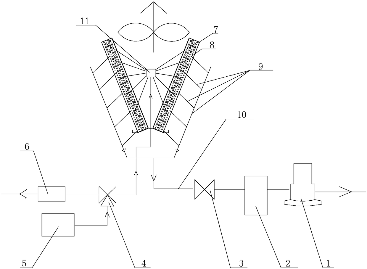
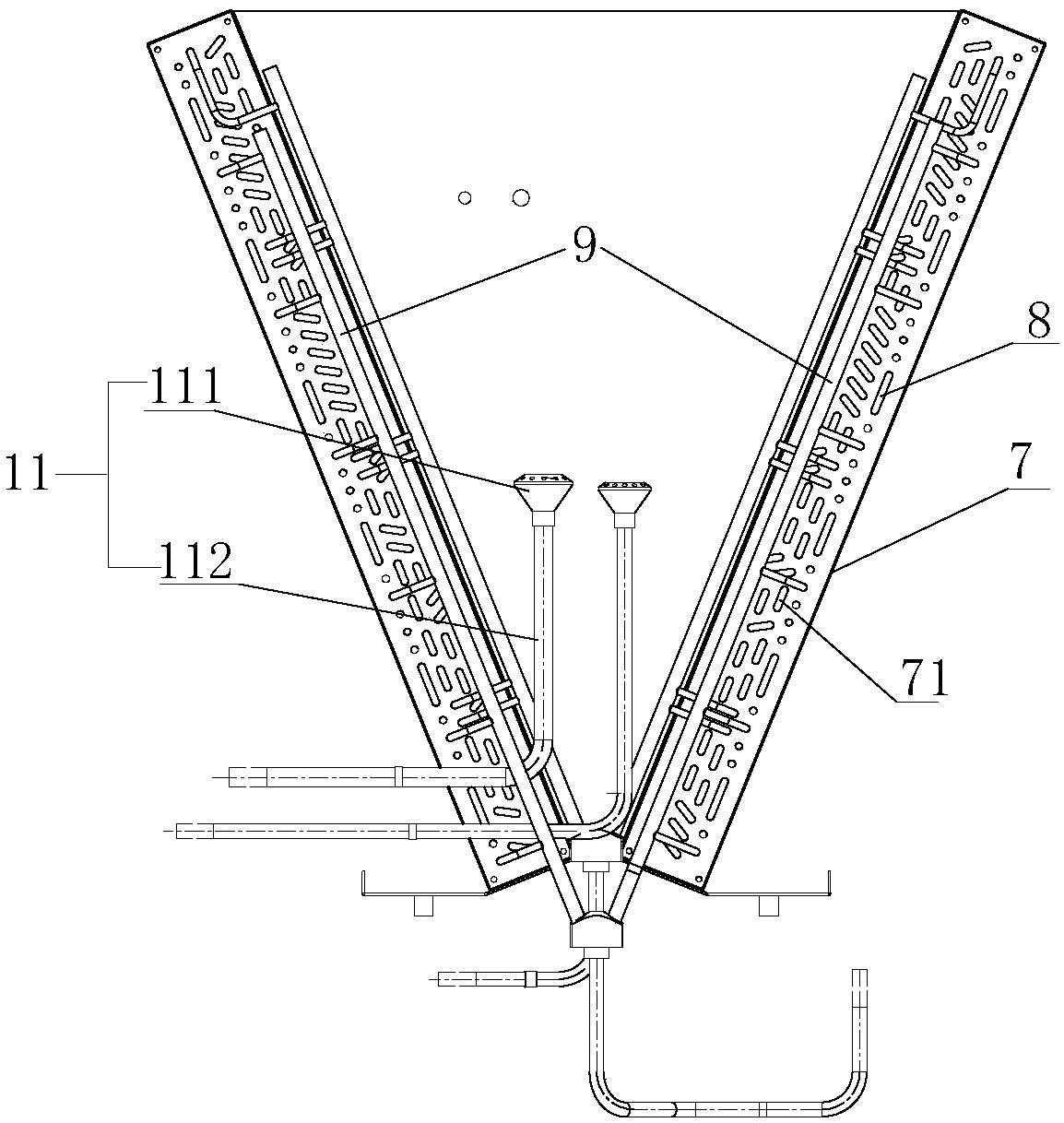
[0046] When the heat pump unit starts to work, the electromagnetic three-way valve 4 is connected to the valve of the liquid separator 11, and the concentrated ammonia solution enters the liquid dispenser 111 in the liquid dispenser 11 through the electromagnetic three-way valve 4, and the liquid dispenser 111 displaces the concentrated ammonia. The solution is evenly distributed to each branch, and enters the defrosting coil 8 inside and outside the finned heat exchanger, and the flow rate of the concentrated ammonia solution is 100g / min.

[0047]At this moment, the surface temperature of the defrosting coil 8 is higher than that of the heat exchange coil 71 , and the heat exchange between the defrosting coil 8 and the heat exchang...

Embodiment 2

[0051] The defrosting method of this embodiment is the same as that of Embodiment 1. The difference from Embodiment 1 is that the concentrated solution used in this embodiment is a concentrated ammonia solution with an ammonia content of 50%, and its freezing point is around -80°C. The flow rate of the concentrated ammonia solution is 400g / min, and the time for passing the concentrated ammonia solution is 3 minutes, and the concentrated ammonia solution is continuously passed after an interval of 30 minutes, and adjusted according to the ambient temperature.

Embodiment 3

[0053] The defrosting method of this embodiment is the same as that of Embodiment 1. The difference from Embodiment 1 is that the concentrated solution used in this embodiment is a concentrated ammonia solution with an ammonia content of 15%, and its freezing point is between -30°C. The flow rate of the concentrated ammonia solution is 500g / min.


PUM

PropertyMeasurementUnit
Freezing pointaaaaaaaaaa

Abstract

The invention discloses a method for delaying frosting on the surface of an absorption unit heat exchanger. A defrosting coiled pipe is additionally arranged in the finned heat exchanger, and a concentrated solution is introduced into the defrosting coiled pipe. According to the method, the concentrated solution is introduced into the defrosting coiled pipe, so that the temperature of the outer surface of the defrosting coiled pipe is higher than the temperature of a heat exchange coiled pipe on the inner side, so that the distance of the air contacting a refrigerant heat exchanger is increased, and the temperature of heat exchanger aluminum foil is increased; the aluminum foil is used as first reduction aluminum foil, the static pressure is increased, the dew point temperature is increased, and the surface temperature of the aluminum foil is still higher than the dew point temperature; therefore, the surface of the absorption type unit heat exchanger is not prone to frosting, and thefrosting is delayed; and the freezing point of the concentrated solution is far lower than the environment temperature, and the phenomenon that the concentrated solution is frozen in the defrosting coiled tube is delayed.

Description

technical field [0001] The invention relates to a technology for delaying frosting, in particular to a method for delaying frosting on the surface of an absorption unit heat exchanger. Background technique [0002] The air source heat pump uses air as a low-temperature heat source to obtain heat from the atmosphere, and the heat exchange equipment and installation are relatively simple. Therefore, it has been widely used in urban development in our country. However, the operating conditions during use are always unsatisfactory, especially in heating operation in low-temperature and high-humidity areas. The main reason for this phenomenon is: when the heat pump operates at a low ambient temperature, the ambient temperature is -5°C to 5°C, and the water vapor in the air is easy to condense on the surface of the air-cooled fin heat exchanger, forming Frost layer, frost on the surface of the outdoor heat exchanger of the air source heat pump leads to poor operation of the unit...

Claims


Application Information

Patent Timeline
IPC IPC(8): F25B47/00
CPCF25B47/006
Inventor 李文张凤学王凤波李群山姚洪李伟栋张洪涛季志国刘恒
Owner SHANDONG QIWEITE SOLAR TECH CO LTD
Why Eureka
Try Eureka