Device for reducing mutual coupling of three-dimensional force sensor in each direction

A mutual coupling, sensor technology, applied in the direction of measuring devices, measuring force components, instruments, etc., can solve the problem of large inter-dimensional coupling, resolution, measurement accuracy, and dynamic characteristics. It is difficult to reach a balance point, Problems such as poor dynamic characteristics, to achieve high sensitivity and eliminate the effect of inter-dimensional coupling problems

Pending Publication Date: 2018-06-05
BEIJING AEROSPACE INST FOR METROLOGY & MEASUREMENT TECH +1
View PDF14 Cites 6 Cited by
  • Summary
  • Abstract
  • Description
  • Claims
  • Application Information

AI Technical Summary

Problems solved by technology

However, it is difficult to reach a balance between resolution, measurement accuracy, inter-dimensional coupling and dynamic characteristics in the design process of 3D force sensors.
Domestic three-dimensional force sensors generally adopt a cylindrical structure, and the resistance strain gauges are arranged at both ends of the cylinder, which ensures that the sensor has high sensitivity, but there are shortcomings such as large inter-dimensional coupling, poor dynamic characteristics, and low stability.
In recent years, some scholars have explored the use of column structures. For example, a column-type three-dimensional force sensor is disclosed in the patent publication number CN200920276179.8. The sensor samples the column structure and arranges the resistance strain gauge in the center of the column. , this technical improvement has improved the stability and dynamic performance of the sensor to a certain extent, but it still cannot solve the problem of inter-dimensional coupling in the three-dimensional force sensor

Method used


Image

  • Device for reducing mutual coupling of three-dimensional force sensor in each direction
  • Device for reducing mutual coupling of three-dimensional force sensor in each direction
  • Device for reducing mutual coupling of three-dimensional force sensor in each direction

Examples


Embodiment Construction

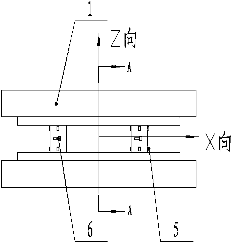
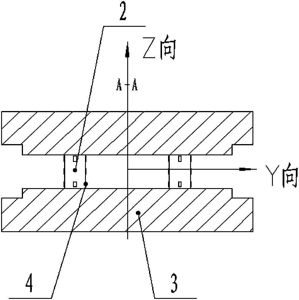
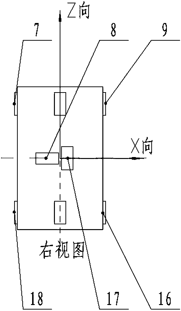
[0022] The present invention will be described in detail below in conjunction with the accompanying drawings and specific embodiments.

[0023] Such as figure 1 As shown in -8, a device for reducing the mutual coupling of three-dimensional force sensors in the present invention includes an upper platen 1, a force transmission column 2, a lower platen 3 and a group of resistance strain gauges. The structure is symmetrical up and down in the axial direction; the shell is hollowed out to form an upper pressure plate 1, a force transmission column 2, and a lower pressure plate 3, and the upper pressure plate 1 transmits the vector force it bears to the lower pressure plate through 4 evenly arranged force transmission columns 2 3; 4 uniformly arranged force transmission columns 2 are the elastic bodies of the three-dimensional force sensor, and each force transmission column 2 is arranged on the four surfaces of the X-direction resistance strain gauge group 5, the Y-direction resis...


PUM


Abstract

The invention relates to a device for reducing mutual coupling of a three-dimensional force sensor in each direction, which comprises an upper pressing plate, force transmission columns and a lower pressing plate, wherein the upper pressing plate transmits the endured vector force to the lower pressing plate through four uniformly-distributed force transmission columns; four surfaces of each forcetransmission column are provided with an X-direction resistance strain gauge group, a Y-direction resistance strain gauge group and a Z-direction resistance strain gauge group; and under effects of external load, the force transmission column generates elastic deformation, and the X-direction resistance strain gauge group, the Y-direction resistance strain gauge group and the Z-direction resistance strain gauge group can sense the deformation amount in each direction. Based on a bending deformation theory, through reasonable spatial arrangement on the resistance strain gauges in each direction, mutual interference among component forces is thus eliminated, the difficult problem of inter-dimension coupling existing in the three-dimensional force sensor is solved, and the measurement accuracy of the three-dimensional force sensor is improved.

Description

technical field [0001] The invention relates to a device for reducing the mutual coupling of three-dimensional force sensors in various directions. Based on the theory of bending deformation, the device arranges the resistance strain gauges in all directions in a reasonable space to eliminate the mutual interference between component forces and solve the problem of the existence of three-dimensional force sensors. To solve the problem of inter-dimensional coupling and improve the accuracy of three-dimensional force sensor measurement. Background technique [0002] Sensors play an important role in industrial production, national defense construction and science and technology. Sensor technology is one of the three pillars of modern information technology. Multi-component force sensors can measure full force information in three-dimensional space, and are widely used in precision assembly, contour tracking, hand coordination, etc., and are widely used in research fields such ...

Claims


Application Information

Patent Timeline
Patent Type & Authority Applications(China)
IPC IPC(8): G01L5/16
CPCG01L5/161
Inventor 高炳涛梅红伟李廷元杨晓伟
Owner BEIJING AEROSPACE INST FOR METROLOGY & MEASUREMENT TECH
Why Eureka
Try Eureka