Kinematic calibration

A technology of kinematics and kinematics models, applied in the field of kinematics calibration, which can solve problems such as inaccuracy

Active Publication Date: 2018-06-05
GF MACHINING SOLUTIONS AG
View PDF16 Cites 3 Cited by
  • Summary
  • Abstract
  • Description
  • Claims
  • Application Information

AI Technical Summary

Problems solved by technology

However, such systems may be less accurate in some cases because kinematic errors are determined based on a subset of positioning errors, i.e. based on measurements taken to determine the kinematic error associated with that axis of rotation, and then repeat the process for the other axis of rotation

Method used


Image

  • Kinematic calibration
  • Kinematic calibration
  • Kinematic calibration

Examples


Embodiment Construction

[0029] figure 1 A typical multi-spindle machine tool 1 with three linear axes X, Y and Z and two rotational axes B and C is shown. The table 2 can move linearly along the axis X. The linear movement along the Y and Z axes takes place via the handpiece 3 on the other hand. The table 2 is rotatable about the axes C and B of rotation. Another axis of rotation A can be implemented in the machine tool 1 , for example by foreseeing the possibility of tilting the handpiece 3 about the X-axis (see arrow A).

[0030] figure 2 show figure 1 The table 2 already shown in FIG. 2 has a fixture 5 mounted on it and has a calibration ball 6 on top of it. The position of the calibration ball 6 (respectively, its center) is measured by a touch probe 7 mounted on the machine head 3 of the machine tool 1 .

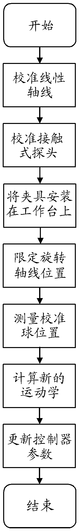
[0031] Hereinafter, the calibration method of the present invention will be described based on examples. image 3 Shows the entire proposed calibration process. Before starting the ki...


PUM


Abstract

The invention relates to kinematic calibration. The present invention relates to a calibration method for numerical controlled machine tools (1), which uses a kinematic model to generate a compensation model for the positioning error occurring with the movement of the linear (X, Y, Z) and rotation axes (B, C, A) of a machine tool (1). The calibration method measures the positions of a calibrationball (6) with a measurement sequence which includes the combined movement of the calibration ball (6) around two rotation axes (C, B or C, A), wherein the measurements around a first rotation axis (C)include at least two rotational position movements around a second axis (B or A).

Description

technical field [0001] The invention relates to a calibration method for a numerically controlled machine tool, which uses a kinematic model to generate a compensation model for positioning errors that occur with the movement of the linear and rotational axes of the machine tool. Background technique [0002] Calibration methods for measuring positioning errors and deriving compensation models to compensate for positioning errors that occur with movement of the machine table or head of the machine tool are well known. Multi-axis machine tools such as milling machines, laser processing machines, grinding machines, electrical discharge machining or lathes have multiple degrees of freedom for moving the table and machine head (machine axis) relative to each other. The degrees of freedom available on multi-axis machines allow and facilitate the machining of workpieces. In particular, complex machining operations of workpieces can be carried out on the same machine tool and in o...

Claims


Application Information

Patent Timeline
Patent Type & Authority Applications(China)
IPC IPC(8): G05B19/404
CPCG05B19/404G05B2219/35408G01B21/042G05B2219/49344G05B2219/50139G01B5/008G05B19/401G05B19/19G05B2219/37001G05B2219/37241G05B2219/37422
Inventor D.斯兰兹J-P.贝苏彻特
Owner GF MACHINING SOLUTIONS AG
Why Eureka
Try Eureka