High pressure liquid flow powder making method

A high-pressure liquid and high-pressure valve technology, applied in the field of mechanical pulverization, can solve problems such as the inability to separate components by components, and achieve the effects of preventing adsorption accumulation, reducing wear, and reducing complexity

Active Publication Date: 2020-09-01
BAOTOU RES INST OF RARE EARTHS +1
View PDF5 Cites 0 Cited by
  • Summary
  • Abstract
  • Description
  • Claims
  • Application Information

AI Technical Summary

Problems solved by technology

Moreover, the jet mill pulverization system can only separate materials by particle size classification, and cannot separate them by components.

Method used


Image

  • High pressure liquid flow powder making method

Examples


Embodiment Construction

[0020] The technical solutions of the present invention will be described in detail below with reference to exemplary implementations. Example embodiments may, however, be embodied in many forms and should not be construed as limited to the embodiments set forth herein; rather, these embodiments are provided so that this disclosure will be thorough and complete, and will fully convey the concept of example embodiments to those skilled in the art.

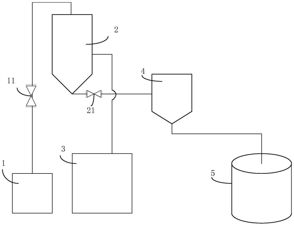
[0021] like figure 1 Shown is a schematic structural view of the high-pressure liquid flow milling device of the present invention.

[0022] The structure of the high-pressure liquid flow pulverizing device includes: liquid material tank 1, high-pressure liquid flow stabilizer 2, high-pressure air pump 3, liquid material breaker 4, high-speed centrifugal classification dryer 5;

[0023] The liquid material box 1 is provided with a material inlet of the liquid material box, and the agitator is arranged inside the liquid material bo...


PUM


Abstract

The invention discloses a high-pressure liquid flow pulverizing device, comprising a liquid feedstock box, a high-pressure liquid flow stabilizer, a high-pressure air pump, a liquid feedstock crusherand a high speed centrifugal grading spin dryer. The invention also discloses a high-pressure liquid flow pulverizing method. According to the device and the method, a high-pressure liquid flow is used for accelerating material particles, so that the material particles are prevented from being adsorbed and accumulated on the inner wall of the device, and the components, dissolved in a liquid medium, of the material can be separated directly.

Description

technical field [0001] The invention relates to a mechanical pulverization technology, in particular to a high-pressure liquid flow pulverization method. Background technique [0002] At present, mechanical pulverization usually adopts a jet mill crushing system. The principle is to use high-speed airflow to make materials collide with each other at high speed and break up. The high-speed material flow will cause greater wear and tear on the inner wall of the device. At the same time, the material is easy to form adsorption accumulation on the inner wall of the device. [0003] In the jet mill crushing system, mechanical vibrating components such as air hammers are usually installed in the parts prone to accumulation to prevent material accumulation. Moreover, the jet mill pulverization system can only separate materials by particle size classification, and cannot separate them by composition. Contents of the invention [0004] The technical problem solved by the present ...

Claims


Application Information

Patent Timeline
Patent Type & Authority Patents(China)
IPC IPC(8): B02C19/06
CPCB02C19/06
Inventor 乔鑫沈雷军王忠志乔君李波高乐乐崔凯璐周志宏
Owner BAOTOU RES INST OF RARE EARTHS
Why Eureka
Try Eureka