Workpiece clamping mechanism

A clamping mechanism and workpiece clamping technology, applied in workpiece clamping devices, manufacturing tools, etc., can solve the problems of workpiece processing, low detection efficiency, increased production cost, and large clamping and fixing time, so as to improve processing and detection. Efficiency, reduce the chance of being scratched, and shorten the effect of clamping time

Pending Publication Date: 2018-06-08
GEER TECH CO LTD
View PDF5 Cites 4 Cited by
  • Summary
  • Abstract
  • Description
  • Claims
  • Application Information

AI Technical Summary

Problems solved by technology

[0003] At present, the functions of the clamping and fixing mechanism for the workpiece are relatively single. After the workpiece is clamped, it can only be processed or inspected in one direction. However, each workpiece needs to be processed or inspected in multiple directions and angles during processing and inspection. If the existing clamping and fixing mechanism wants to process or detect the entire workpiece, it can only process or detect one orientation of the workpiece, remove the workpiece, change the orientation and re-clamp and fix it, and then process or inspect, resulting in processing Or to detect a workpiece to be fixed multiple times, it takes a lot of clamping and fixing time, resulting in low efficiency of workpiece processing and testing; at the same time, it will also increase the probability of scratching the surface of the workpiece due to multiple clamping and fixing, resulting in The product quality of the workpiece decreases, the yield rate is low, and the production cost increases

Method used


Image

  • Workpiece clamping mechanism
  • Workpiece clamping mechanism
  • Workpiece clamping mechanism

Examples


Embodiment Construction

[0025] Below in conjunction with accompanying drawing and embodiment, further elaborate the present invention.

[0026] The orientations involved in this specification are all subject to the orientations shown in the drawings, which only represent relative positional relationships, not absolute positional relationships.

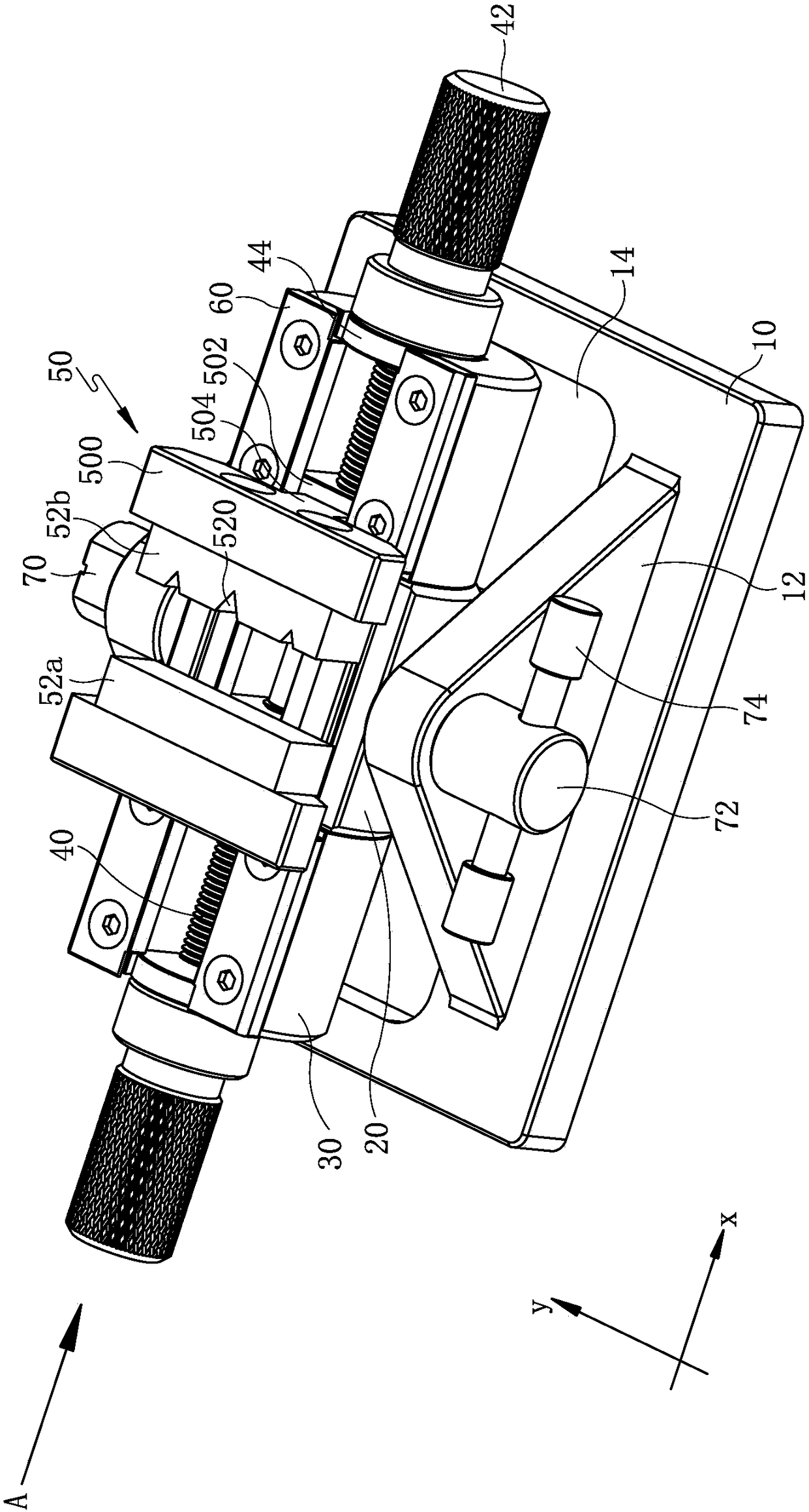
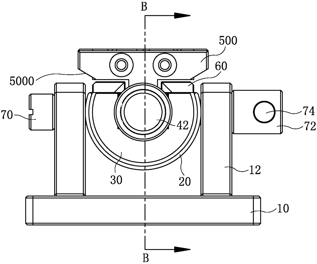
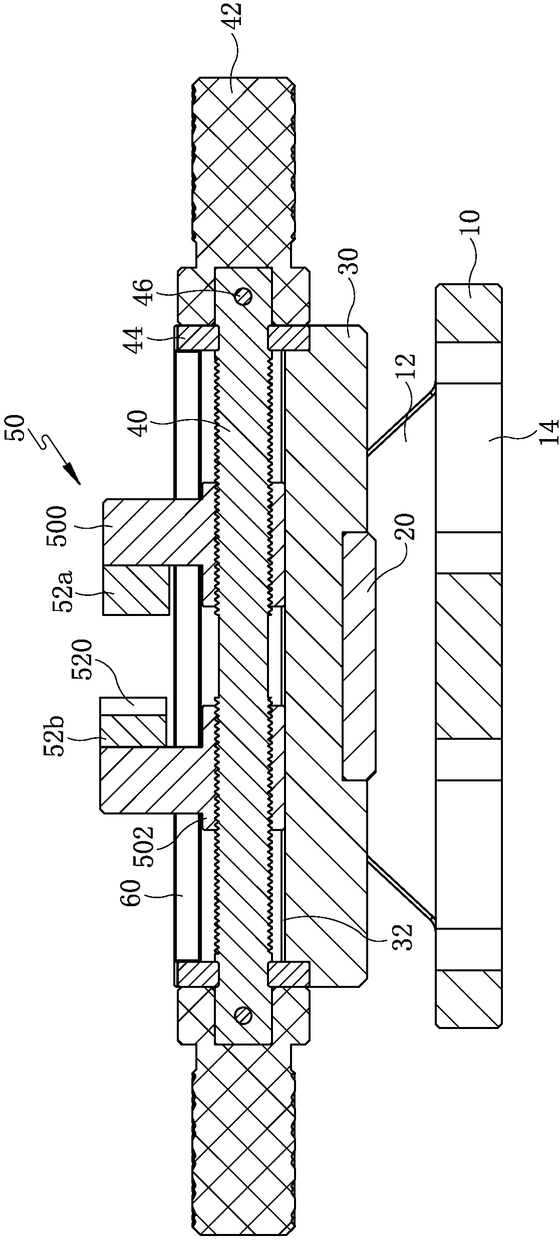
[0027] Such as figure 1 As shown, a workpiece clamping mechanism includes a base 10 on which a bracket 20 that can rotate around the y-axis is installed, such as Figure 4 As shown, the bracket 20 is provided with an arc-shaped chute whose axial direction is the x-axis direction. In this embodiment, the bracket 20 is an arc-shaped plate whose longitudinal section is a part removed. On the base 10, an arc-shaped chute whose axial direction is the x-axis direction is formed on the inner side thereof. A rotary cylinder 30 that can rotate around the x-axis is installed in the arc-shaped chute. The axial direction of the rotary cylinder 30 is the x direction, th...


PUM


Abstract

The invention discloses a workpiece clamping mechanism, and relates to the technical field of workpiece production auxiliary equipment. The workpiece clamping mechanism comprises a base, a bracket capable of rotating around the y axis is installed on the base, and an arc sliding groove adopting the x axis direction as the axial direction is formed in the bracket; a rotating cylinder capable of rotating around the x axis is rotationally installed inside the arc sliding groove, the axial direction of the rotating cylinder is the x axis direction, two clamping blocks are installed on the rotatingcylinder, and at least one of the two clamping blocks can axially reciprocate and slide along the rotating cylinder. The workpiece clamping mechanism solves the technical problems that in the prior art, when workpieces need to be machined and detected in multiple directions, repeated clamping is needed, and the clamping efficiency is low, multi-directional machining or detecting of workpieces canbe achieved only through one-time clamping, the machining and detecting efficiency of the workpieces is improved, meanwhile, the probability that the workpieces are scratched is lowered, the productyield is increased, and the production cost of an enterprise is lowered.

Description

technical field [0001] The invention relates to the technical field of workpiece production auxiliary equipment, in particular to a workpiece clamping mechanism. Background technique [0002] In the field of mechanical processing, a workpiece requires multiple processing and testing procedures from the blank to the finished product. The processing procedures include cutting, cutting, drilling, etc. in the previous process, and polishing, grinding, wire drawing, etc. in the post-processing process; The size, hardness, etc. of the workpiece are tested. Whether it is in the processing process or in the testing process, the workpiece must be clamped and fixed effectively to be able to perform corresponding operations. [0003] At present, the functions of the clamping and fixing mechanism for the workpiece are relatively single. After the workpiece is clamped, it can only be processed or inspected in one direction. However, each workpiece needs to be processed or inspected in m...

Claims


Application Information

Patent Timeline
Patent Type & Authority Applications(China)
IPC IPC(8): B25B11/00
CPCB25B11/00
Inventor 陈超杰
Owner GEER TECH CO LTD
Why Eureka
Try Eureka