Novel flexible weak current cabinet side metal wiring unit, wiring cabinet and wiring method
A technology for metal wiring and weak current cabinets, which is applied to electrical components and other directions, can solve the problems of difficulty in line inspection work and drawing and assembly line work, long construction time, and increased operation difficulty, and achieves convenient and fast line inspection and line replacement. The effect of using a high degree of safety and rapid structuring of wiring
- Summary
- Abstract
- Description
- Claims
- Application Information
AI Technical Summary
Problems solved by technology
Method used
Image
Examples
Embodiment 1
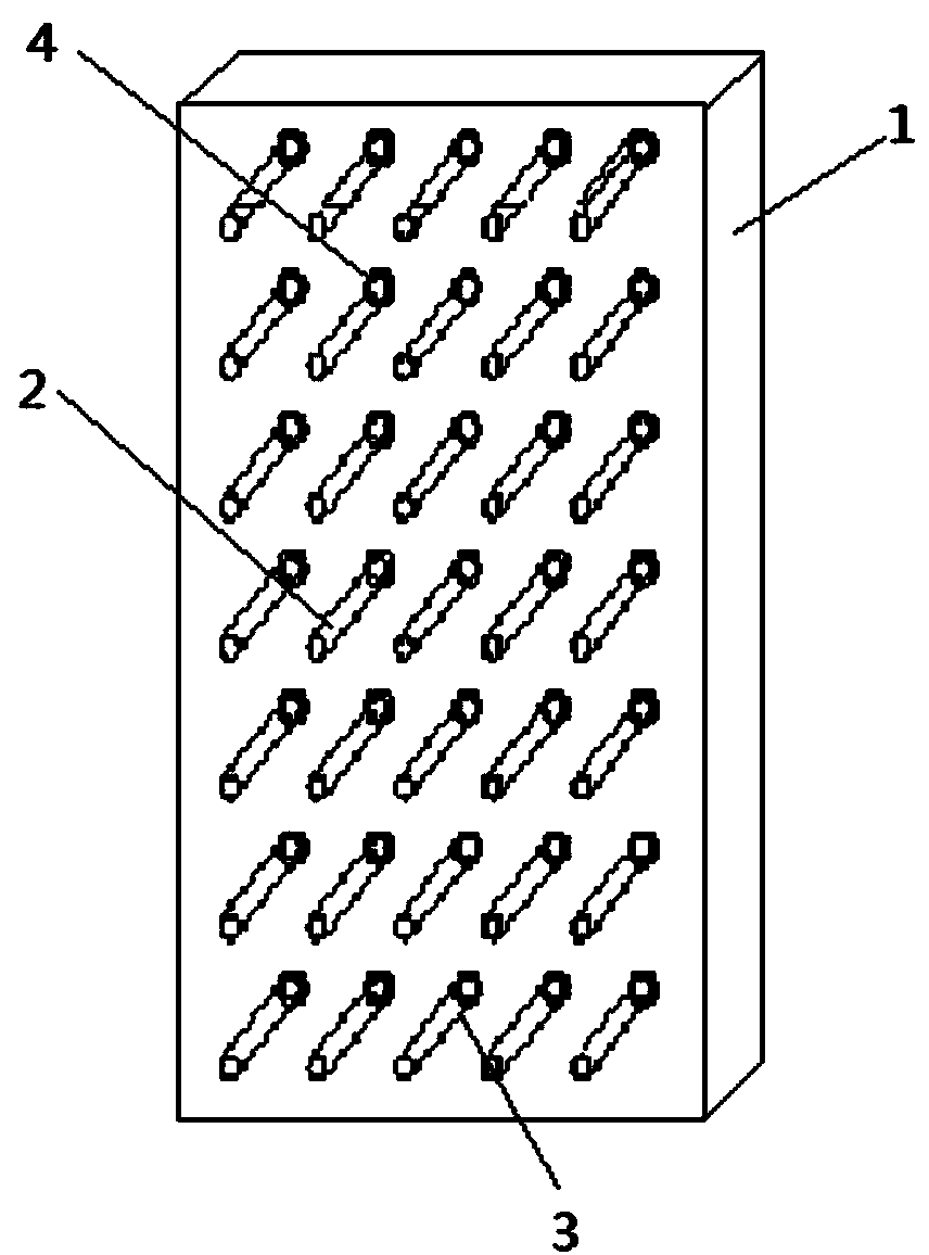
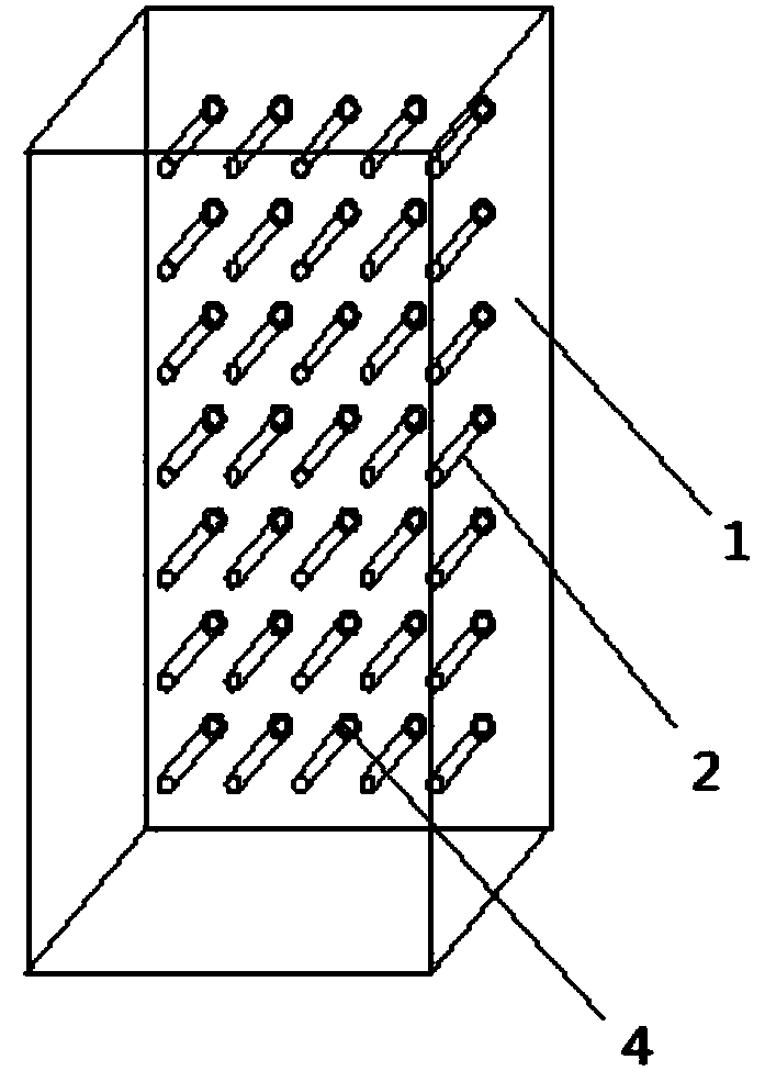
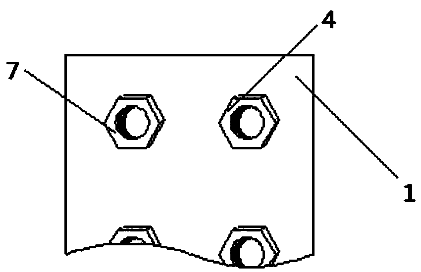
[0037] Reference figure 1 In this embodiment, the new-style flexible metal wiring unit on the side of the weak current cabinet includes a metal fixing plate 1. On the metal fixing plate 1, 5 rows of mounting member groups 3 are arranged 6 cm in parallel, and each row of mounting member groups 3 Including 7 mounting parts 4 with a spacing of 10 cm, all 35 mounting parts 4 are uniformly arranged in a square matrix structure. Reference image 3 , The mounting part 4 in this embodiment is designed as a nut, the nut is directly integrated with the metal fixing plate, and the nut protrudes from the metal fixing plate; Figure 4 , The metal winding rod 2 is fixed on the metal fixing plate 1 by using a screw thread to cooperate with a nut. The length of each metal winding rod 2 is 10cm, and the user can freely choose the length of the metal winding rod 2 between 10cm and 40cm according to the actual situation such as the number of windings, diameter, etc., such as 12cm, 20cm, 30cm, 35c...
Embodiment 2
[0041] Reference Figure 5 In the new flexible metal wiring unit on the side of the weak current cabinet in this embodiment, the surface of the metal winding rod 2 is provided with a plurality of arc cable insertion grooves 5 of equal width, and each arc cable insertion groove 5 is ring-shaped Structure, so that the surface of the metal winding rod 2 has a wave structure. Each cable occupies one of the arc-shaped cable insertion grooves 5, so that its position is relatively fixed with the metal winding rod 2.
Embodiment 3
[0043] Reference Figure 5 In order to facilitate the loading and unloading of the metal winding rod 2, in this embodiment, there is a rotating handle 6 at the outer end of the metal winding rod 2, so that the operator can easily rotate the metal winding rod 2. At the same time, it is also possible to replace the rotating handle 6 with a manual electric rotating interface, and use an external electric or manual rotating device to achieve the purpose of faster and more convenient operation.
PUM
 Abstract
Description
Claims
Application Information
 - R&D
- Intellectual Property
- Life Sciences
- Materials
- Tech Scout
- Unparalleled Data Quality
- Higher Quality Content
- 60% Fewer Hallucinations
Browse by: Latest US Patents, China's latest patents, Technical Efficacy Thesaurus, Application Domain, Technology Topic, Popular Technical Reports.
© 2025 PatSnap. All rights reserved.Legal|Privacy policy|Modern Slavery Act Transparency Statement|Sitemap|About US| Contact US: help@patsnap.com


