Active filter RC time constant calibration circuit and method

A technology for calibrating circuits and source filters, applied in single-port active networks, and improving the network in order to reduce the impact of temperature changes, and can solve problems such as RC time constant drift of active filters

Inactive Publication Date: 2018-06-08
MIARTECH
View PDF4 Cites 3 Cited by
  • Summary
  • Abstract
  • Description
  • Claims
  • Application Information

AI Technical Summary

Problems solved by technology

However, depending on the manufacturing process, power supply voltage, and temperature environment of the capacitor and resistor, there may be an error of up to ±20% between t

Method used


Image

  • Active filter RC time constant calibration circuit and method
  • Active filter RC time constant calibration circuit and method
  • Active filter RC time constant calibration circuit and method

Examples


Embodiment Construction

[0023] In order to make the above objects, features and advantages of the present invention more comprehensible, specific implementations of the present invention will be described in detail below in conjunction with the accompanying drawings.

[0024] In the following description, many specific details are set forth in order to fully understand the present invention, but the present invention can also be implemented in other ways than those described here, so the present invention is not limited by the specific embodiments disclosed below.

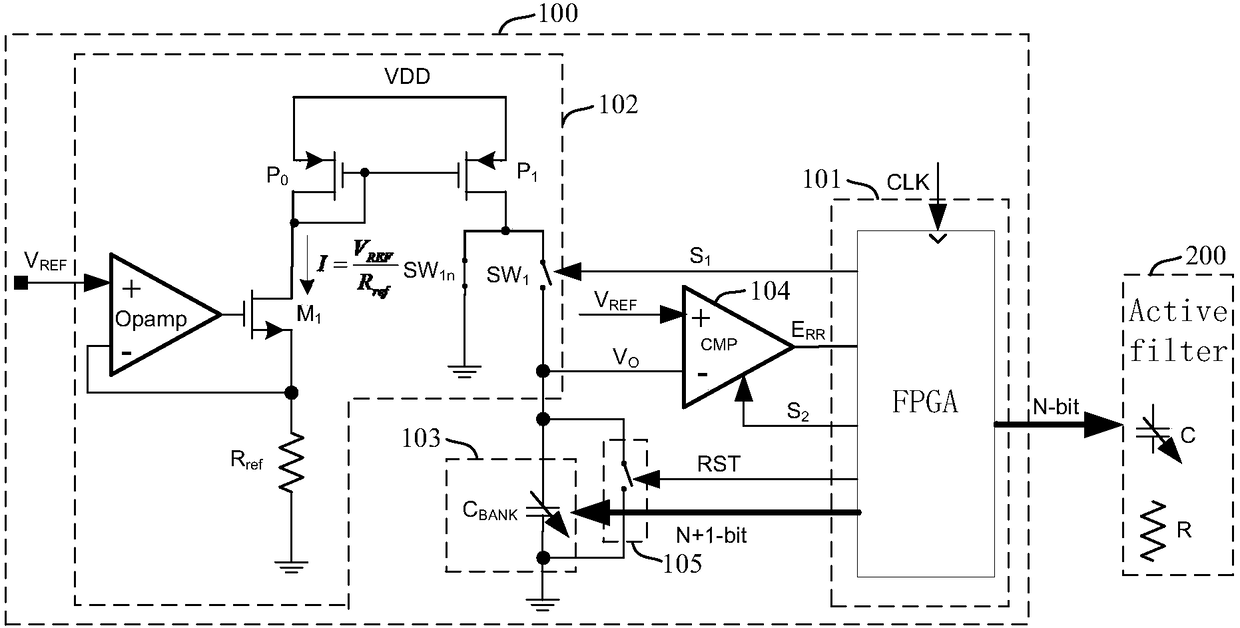
[0025] figure 1 It is a structural schematic diagram of an RC time constant calibration circuit of an active filter of the present invention. refer to figure 1 , the RC time constant calibration circuit 100 of the active filter (hereinafter referred to as the calibration circuit 100) includes a control circuit 101, a constant current source charging circuit 102, a calibration capacitor array C BANK 103 and comparator 104.

[0026] fi...


PUM


Abstract

The invention provides an active filter RC time constant calibration circuit and method. The method is characterized by charging a calibration capacitor array CBANK with a constant current, charging time being T; and measuring an actual capacitance value through the voltage VO of the calibration capacitor array CBANK, and correcting the capacitance value of a capacitor array C in an active filter,wherein the calibration capacitor array CBANK and the capacitor array C form a proportional relation, and the charging time T is related to the expected RC time constant of the active filter.

Description

technical field [0001] The invention mainly relates to a circuit parameter calibration technology, in particular to an RC time constant calibration technology of an active filter. Background technique [0002] Because the active RC filter has good linearity, dynamic range and noise performance, and the implementation method is simple, it is widely used in communication systems and the like. In order to meet the requirements of the communication system for frequency accuracy within ±3%, the RC time constant of the active filter needs to meet the corresponding accuracy requirements. However, depending on the manufacturing process, power supply voltage, and temperature environment of the capacitor and resistor, there may be an error of up to ±20% between the actual value and the calibrated value, resulting in the drift of the RC time constant of the active filter , so the RC time constant of the active filter must be calibrated. Contents of the invention [0003] The techni...

Claims


Application Information

Patent Timeline
IPC IPC(8): H03H11/46H03H11/54
CPCH03H11/46H03H11/54
Inventor 司翠英
Owner MIARTECH
Why Eureka
Try Eureka