
Knee endoprosthesis for replacing at least parts of the knee joint

A technology of prosthesis and knee, applied in the field of knee prosthesis, can solve problems such as looseness

Inactive Publication Date: 2018-06-08
CERAMTEC
View PDF6 Cites 0 Cited by
  • Summary
  • Abstract
  • Description
  • Claims
  • Application Information

AI Technical Summary

Problems solved by technology

[0004] It has been proved in practice that although the anatomical and kinematic situation can be simulated relatively well by a knee endoprosthesis of this type of construction, due to a total of three friction surfaces and an unfavorable material technology Sliding surfaces that are matched to one another inherently have an increased material wear compared to the fixed meniscal part and thus have an increased risk of the implant loosening

Method used


Image

  • Knee endoprosthesis for replacing at least parts of the knee joint
  • Knee endoprosthesis for replacing at least parts of the knee joint
  • Knee endoprosthesis for replacing at least parts of the knee joint

Examples


Embodiment Construction

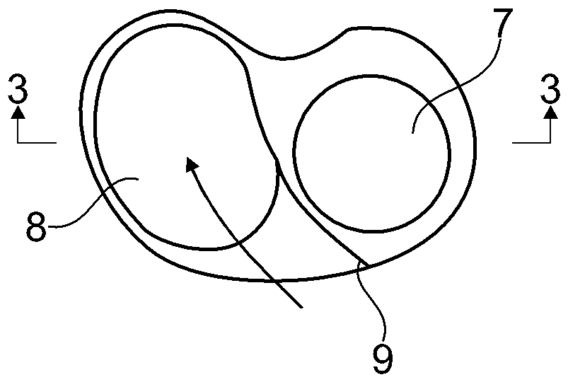
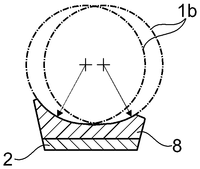
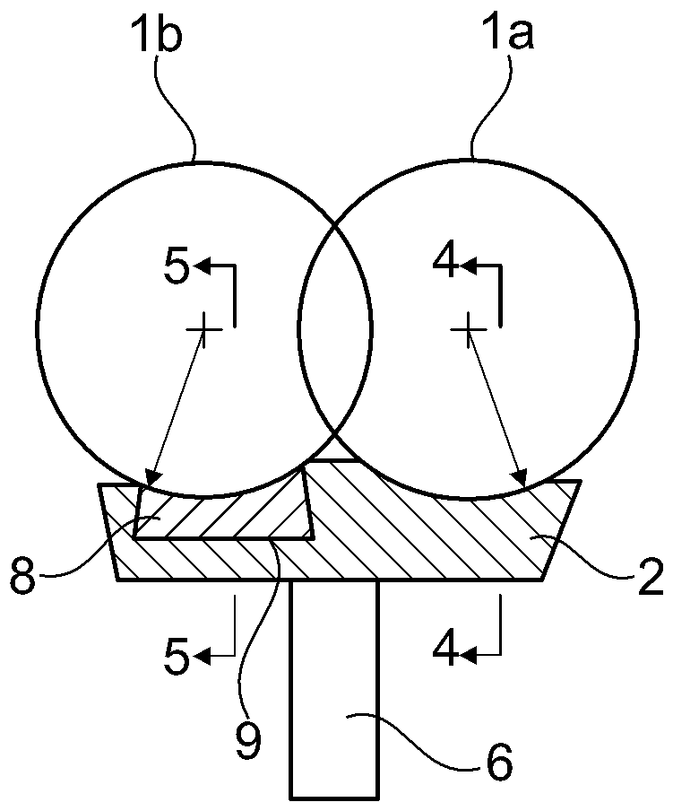
[0016] figure 1 shows a knee endo-articular prosthesis according to the invention with a femoral component having a femoral component 1 consisting of two condylar surfaces 1a, 1b for anchoring in the distal femur, and the knee endoprosthesis with tibial component 2 for anchoring at the proximal tibia. The tibial component is formed by the tibial plateau, on the underside of which faces the tibia a pin 6 is arranged for anchoring. On the upper side, that is to say on the side of the tibial plateau facing the femoral component 1 , an inner bearing shell 7 is arranged according to the invention as an integral part of the ceramic tibial plateau. The inner carrier shell 7 is spherical in shape. Both the femoral component 1 and the tibial component 2 are made of solidly sintered ceramic, that is to say ceramic components. This provides a ceramic / ceramic sliding pair which is virtually wear-free even under prolonged use. Arranged laterally next to the medial bearing shell 7 is a ...


PUM


Abstract

The invention relates to a knee endoprosthesis comprising a femoral component (1) which has two condyle surfaces (1a, 1b) for anchoring on the distal femur, comprising a tibial component (2) for anchoring on the proximal tibia, and comprising sliding surfaces between the two components (1, 2). The aim of the invention is a knee endoprosthesis which has as little abrasion as possible while optimally reproducing the anatomical and kinematic properties of the natural knee joint, in particular by means of suitable combinations of materials and by reducing the abrasion-generating surfaces. This isachieved in that the entire femoral component (1), but at least the condyle surfaces (1a, 1b) thereof, for articulating with the tibial component (2) consists of a rigidly sintered ceramic, and the tibial component (2) comprises a tibial baseplate (11) consisting of a rigidly sintered ceramic, said baseplate having a medial spherical bearing shell (7) on the baseplate upper face facing the femoralcomponent (1). The medial spherical bearing shell (7) is an integral component of the tibial baseplate (11) and is integrally formed with the tibial baseplate, and the articulation surface of the medial femur condyle (1a) is likewise spherically shaped and together with the medial spherical bearing shell (7) constitutes a congruent ball joint. A bearing shell (8) which allows the rotation of thefemoral component (1), is made of multiple radii in the anterior-posterior direction, and is arranged non-congruently with the femur condyle (1b) is arranged laterally adjacent to the medial sphericalbearing shell (7), said bearing shell (8) either being formed integrally with the tibial baseplate (11) or being an inlay which is movable relative to the tibial baseplate (11).

Description

technical field [0001] The invention relates to a knee endoprosthesis (Knieendopothese) with a femoral component with two condyle surfaces (Kondylenfläche) for anchoring at the femur at the far side and with a femur component for anchoring at the proximal side A tibial component at the tibia with a sliding surface between the two components. Background technique [0002] The present invention generally relates to improvements in knee endoprostheses for replacing at least part of the knee joint. A knee endoprosthesis for partial or total knee joint replacement typically consists of a femoral component anchored at the distal femur and a tibial component anchored at the proximal tibia, wherein the tibial component Contains an insert or meniscus component for engagement with the femoral component. [0003] In document US 6,013,103 a knee endoprosthesis is described in which the surface of the tibial part is configured planarly and allows movement of the meniscus part in this p...

Claims


Application Information

Patent Timeline
Patent Type & Authority Applications(China)
IPC IPC(8): A61F2/38A61L27/10A61F2/30
CPCA61F2/3859A61F2/385A61F2/3845A61L27/10A61F2/38A61F2/389A61F2002/30968A61L27/06A61F2002/30649A61F2002/30878A61F2002/30934A61L2430/02A61F2310/00179A61L27/14A61L2430/24A61F2002/30242A61F2230/0071A61F2002/30133A61F2/30771A61F2/3868A61F2002/3082
Inventor W.布勒默
Owner CERAMTEC
Learn More