Heat exchanger
A heat exchanger and heat exchange fluid technology, applied in heat exchange equipment, water heaters, indirect heat exchangers, etc., can solve problems such as inability to absorb thermal expansion difference, flow path rupture, etc., to prevent rupture and prevent heat exchange efficiency Falling effect
- Summary
- Abstract
- Description
- Claims
- Application Information
AI Technical Summary
Problems solved by technology
Method used
Image

Examples
Embodiment 1
[0039] 〔Heat exchange unit〕
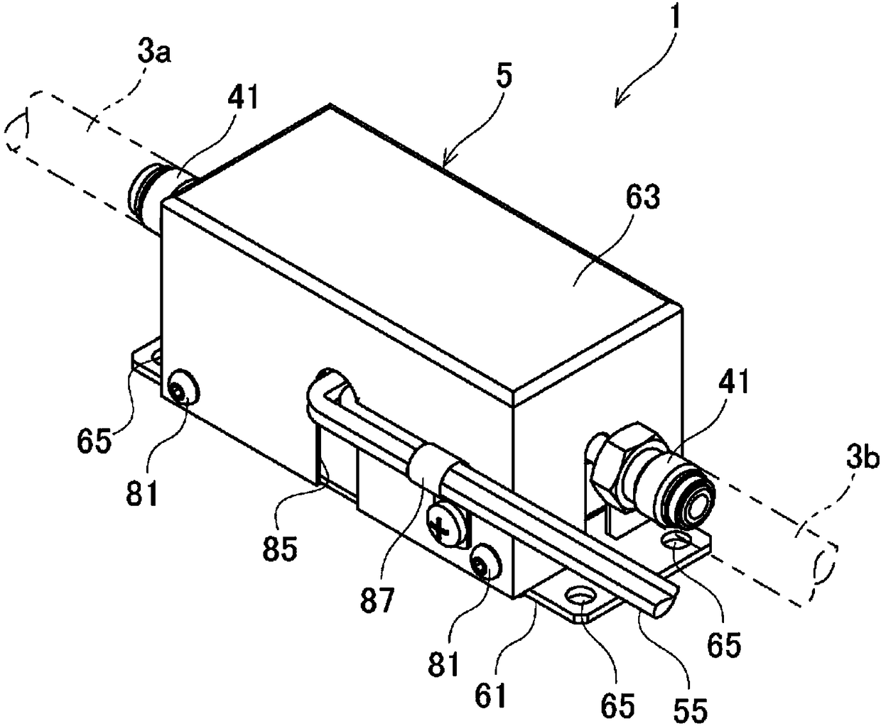
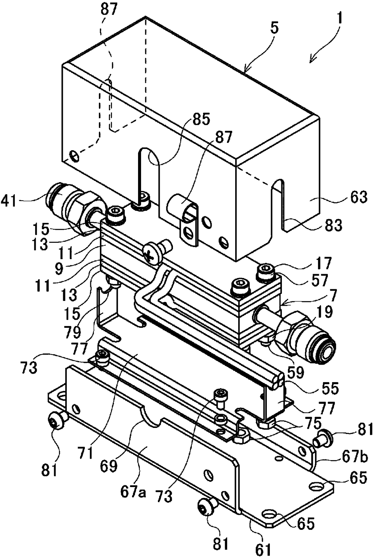
[0040] figure 1 It is a perspective view of a heat exchange unit with a heat exchanger according to Embodiment 1 of the present invention. figure 2 It is an exploded perspective view of the heat exchange unit.
[0041] The heat exchange unit 1 of the present embodiment is installed in the middle of the pipes 3a and 3b through which the heat exchange fluid flows, and is used in a state of being fixed to a wall or the like, for example. In this heat exchange unit 1 , the heat-exchanged fluid flowing in from the pipe 3 a on the upstream side passes through the inside and flows out to the pipe 3 b on the downstream side. At this time, the heat exchange unit 1 will be heated or cooled by the heat exchange fluid for temperature control or temperature adjustment. In this embodiment, the heat exchanged fluid is heated by the heat exchange unit 1 .
[0042] The fluid to be heat exchanged is not particularly limited, and is corrosive acids such as hydr...
Embodiment 2
[0120] Figure 14 It is a sectional view of the heat exchanger according to Example 2 of the present invention. In the second embodiment, the same symbols are used for the components corresponding to those of the first embodiment, or the symbols A are added to the same symbols, and repeated explanations are omitted.
[0121] In the heat exchanger 7A of this embodiment, only one heat transfer plate 11Aa of the pair of heat transfer plates 11Aa, 11Ab is provided with the heat conductor 51A. The heat transfer plate 11Ab does not have a heat conductor, and is constituted only by a plate-shaped plate main body 49 .
[0122] Compared to Example 1, the heat conductor 51A extends in the longitudinal direction, and defines a gap G1 with the other heat transfer plate 11Ab in the insertion direction.
[0123] In this second embodiment, the same effect as that of the first embodiment can be obtained.
Embodiment 3
[0125] Figure 15 It is a schematic diagram showing a part of the flow path of the heat exchanger body in Example 3 of the present invention. In Embodiment 3, the same symbols are used for the components corresponding to those in Embodiment 1, or the symbols B are added to the same symbols, and repeated descriptions are omitted.
[0126] In this embodiment, the outer side of the folded shape of the folded portion 33B of the flow path 23B is formed into a curved shape with no corners as a whole.
[0127] Therefore, in Example 3, turbulent flow can be generated by the inner corner 43 of the folded shape of the folded portion 33B, and excessive turbulent flow can be more reliably prevented by the curved shape without any corners on the outside of the folded shape. Therefore, in this embodiment, the pressure loss of the heat-exchanged fluid can be suppressed to a minimum, and the turbulent flow can be reliably generated.
[0128] In addition, Example 3 can also obtain the same f...
PUM
 Abstract
Description
Claims
Application Information
 - Generate Ideas
- Intellectual Property
- Life Sciences
- Materials
- Tech Scout
- Unparalleled Data Quality
- Higher Quality Content
- 60% Fewer Hallucinations
Browse by: Latest US Patents, China's latest patents, Technical Efficacy Thesaurus, Application Domain, Technology Topic, Popular Technical Reports.
© 2025 PatSnap. All rights reserved.Legal|Privacy policy|Modern Slavery Act Transparency Statement|Sitemap|About US| Contact US: help@patsnap.com