
Temperature control device of electrical energy storage unit

A technology of temperature control device and energy storage unit, applied in the direction of battery temperature control, electrical components, batteries, etc., to prevent heating and reduce isolation overhead

Inactive Publication Date: 2018-06-08
ROBERT BOSCH GMBH
View PDF14 Cites 0 Cited by
  • Summary
  • Abstract
  • Description
  • Claims
  • Application Information

AI Technical Summary

Problems solved by technology

Temperature management is a particular challenge for these so-called high-temperature batteries, since their operating temperatures are typically significantly higher than ambient

Method used


Image

  • Temperature control device of electrical energy storage unit
  • Temperature control device of electrical energy storage unit
  • Temperature control device of electrical energy storage unit

Examples


Embodiment Construction

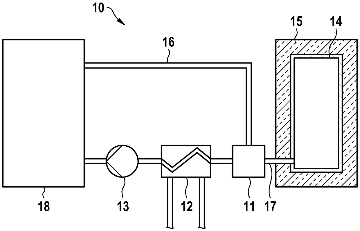
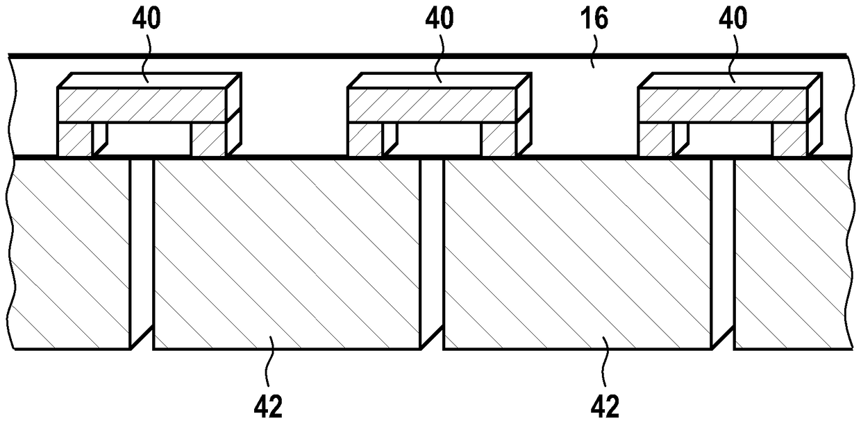
[0030] figure 1According to a first exemplary embodiment, a temperature control device 10 is shown schematically with a cooling circuit, which is connected, for example, via a suitable fluid line 16 to an electrical energy storage unit 18 . A fluid storage container 14 surrounded by thermal insulation 15 is connected to the cooling circuit via a valve 11 . In this case, the fluid circulating in the cooling circuit can be a gas or a liquid, for example a water / glycol mixture. When connecting the insulated fluid storage container, it is advantageous to design the connecting line 17 between the valve 11 and the fluid storage container 14 short in order to minimize possible heat losses. In order to heat or cool the fluid circulating in the cooling circuit, a heat exchanger 12 is integrated into the circuit. A pump 13 in the cooling circuit circulates the fluid. Corresponding adjustment commands can be generated, for example, in the figure 1 The controller not shown in the tran...


PUM


Abstract

The invention relates to a temperature control device (10) of an electrical energy storage unit (42), comprising a fluid-based cooling circuit, wherein the temperature control device (10) has a fluidreservoir (14), which is connected to the cooling circuit by means of a shut-off element (11) and is at least partially surrounded by thermal insulation (15). The invention further relates to a methodfor operating a temperature control device (10), and to an electrical energy storage system.

Description

technical field [0001] The invention relates to a temperature control device for an electric energy storage unit, a method for operating a temperature control device for an electric energy storage unit and an electric storage unit according to the preambles of the independent patent claims energy system. Background technique [0002] The temperature management of batteries, in particular batteries installed in motor vehicles, is an important aspect, since it can decisively influence the reliability, efficiency and improvement of the service life of said batteries. Further development of this technology is therefore also of great interest from the point of view that future batteries may have to be operated at higher temperature levels than is the case with currently frequently used lithium-ion technology. Temperature management is a particular challenge for these so-called high-temperature batteries, since their operating temperature is typically significantly higher than th...

Claims


Application Information

Patent Timeline
Patent Type & Authority Applications(China)
IPC IPC(8): H01M10/6568H01M10/659H01M10/658H01M10/6553H01M10/6556
CPCH01M2220/10H01M2220/20H01M10/625H01M10/627H01M10/6553H01M10/6556H01M10/6568H01M10/658H01M10/659Y02E60/10H01M10/613H01M10/63H01M10/656
Inventor R.拉姆赛尔M.雷德勒M.科尔贝格尔
Owner ROBERT BOSCH GMBH
Learn More