Supercharge Your Innovation With Domain-Expert AI Agents!

Bi-directional current sensing circuit

A technology of current sensing and forward current, which is applied in the direction of only measuring current, electrical components, and adjusting electrical variables, etc., which can solve the problems of increasing cost, design complexity, and occupying integrated die area.

Inactive Publication Date: 2018-06-08
QUALCOMM INC
View PDF3 Cites 2 Cited by
  • Summary
  • Abstract
  • Description
  • Claims
  • Application Information

AI Technical Summary

Problems solved by technology

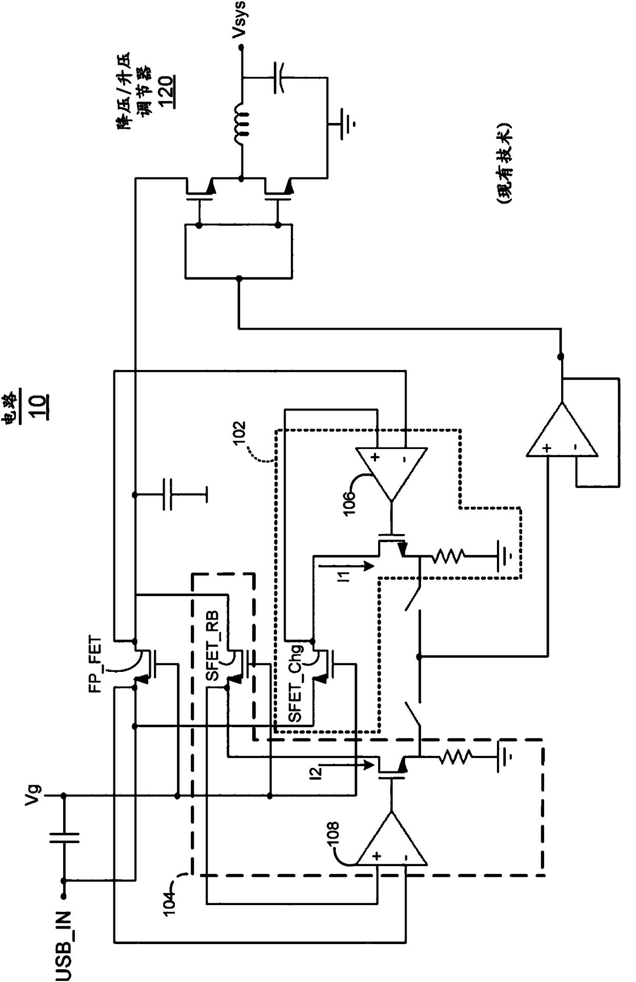
[0010] However, such a circuit occupies a significant amount of integrated die area, requires two separate current sense operational amplifiers 106 and 108, thereby increasing cost and design complexity

Method used


Image

  • Bi-directional current sensing circuit
  • Bi-directional current sensing circuit
  • Bi-directional current sensing circuit

Examples


Embodiment Construction

[0029] Throughout the description, for purposes of explanation, numerous specific details are set forth in order to provide a thorough understanding of the present invention. It will be apparent, however, to one skilled in the art that the techniques described herein may be practiced without some of these specific details. In other instances, well-known structures and devices may be shown in block diagram form in order to avoid obscuring the underlying principles of the invention.

[0030]Additionally, provided below is a description of an example system upon which embodiments described herein may be implemented. Although some elements may be depicted as separate components, in some cases one or more of the components may be combined into a single device or system. Similarly, although a certain function may be described as being performed by a single element or component within a system, that functionality may in some cases be performed by multiple components or elements work...


PUM


Abstract

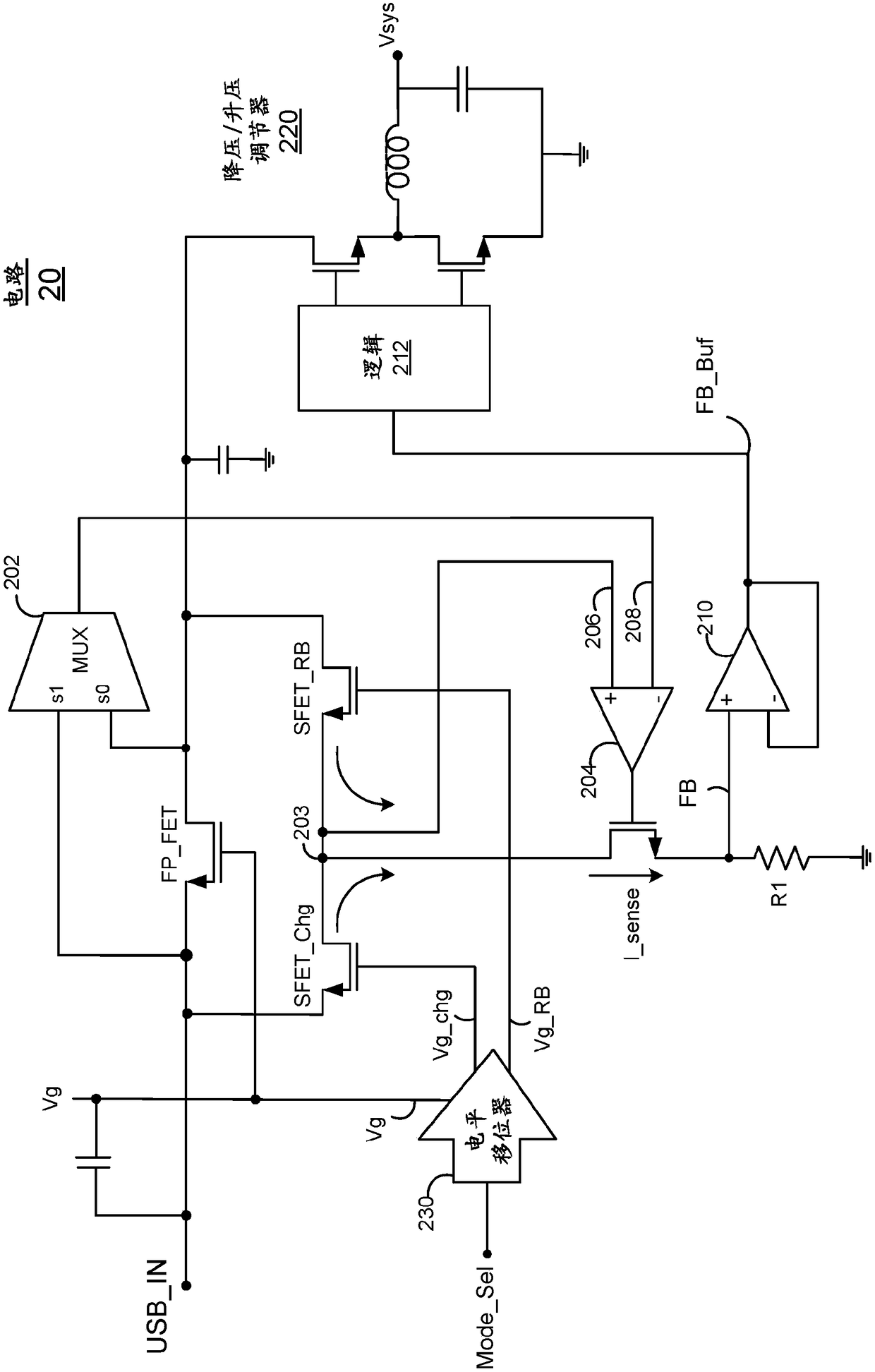
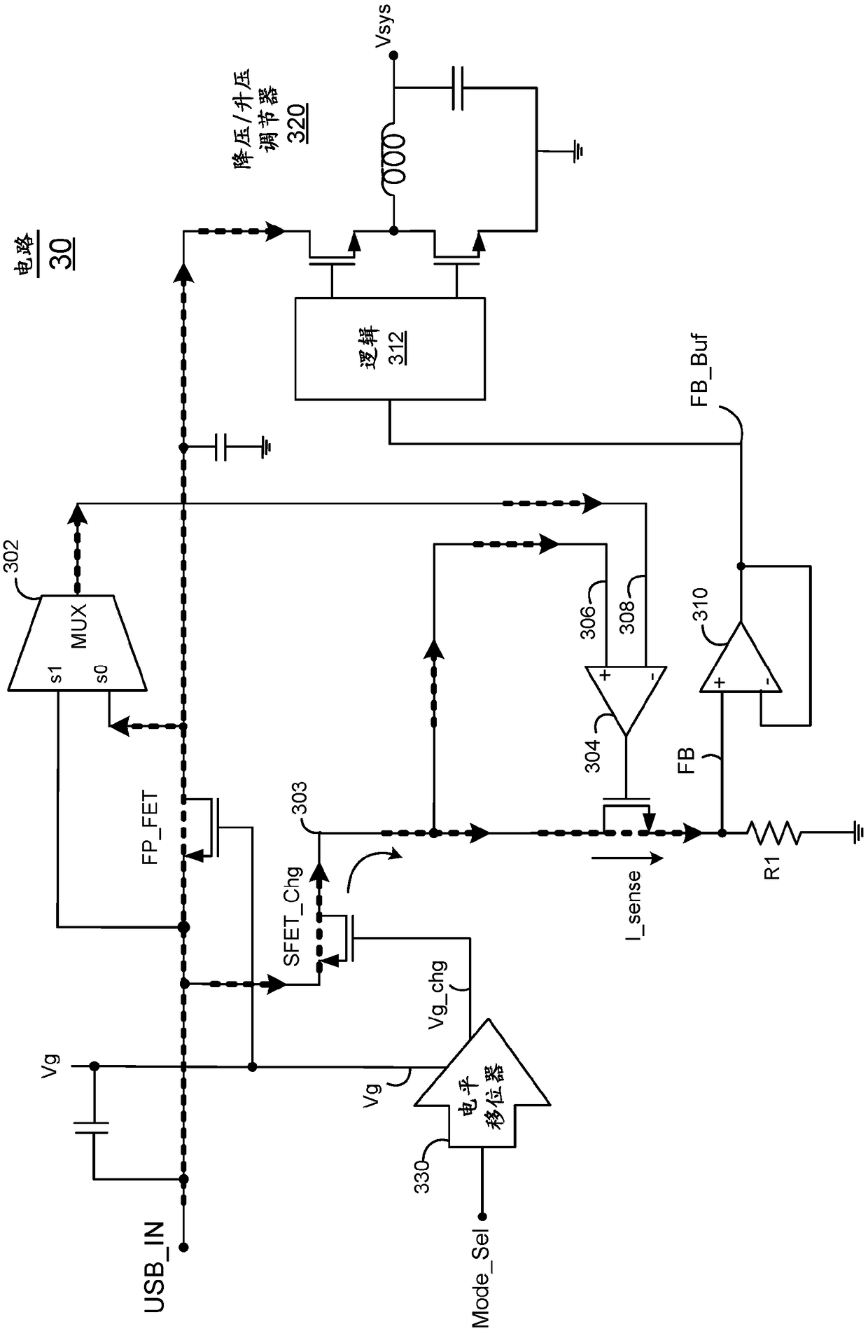
The embodiments of the invention relates to an improved circuit technique for sensing current conducting in a power transistor coupled with an input power supply. The circuit includes a bi-directionalcurrent sensing circuit using current sensing transistor gate control. The circuit includes a forward current sensing transistor to sense current conducting in the power transistor during forward mode current of the circuit and a reverse boost current sensing transistor to sense current conducting during reverse current mode of the circuit. A level shifter is also provided with complementary outputs to either turn on the forward current sensing transistor or turn off the reverse boost current sensing transistor when the circuit is in forward current mode, or to turn off the forward current sensing transistor and turn on the reverse boost current sensing transistor when the circuit is in reverse current mode.

Description

[0001] Cross References to Related Applications [0002] This application claims priority to US Application No. 14 / 871,636, filed September 30, 2015, the contents of which are hereby incorporated by reference in their entirety for all purposes. technical field [0003] At least some embodiments disclosed herein relate generally to electronic circuits, and more particularly to improved bidirectional current sensing circuits and methods. Background technique [0004] Power conversion circuitry is employed in many applications, such as in portable devices, which utilize an external power source to operate the device and / or charge the device's internal battery. In many cases, the current drawn from the source may need to be limited according to published specifications for the device to draw power from the connection. For example, with a Universal Serial Bus (USB) power supply connection, a portable device may be limited to draw a maximum of 500 mA from a USB 2.0 connection. ...

Claims


Application Information

Patent Timeline
Patent Type & Authority Applications(China)
IPC IPC(8): H02M3/156G05F1/10
CPCG05F1/10H02M3/156H02M1/0009G01R19/0092
Inventor R·K·冈特雷迪Z·吴Z·朱G·瓦伦蒂诺
Owner QUALCOMM INC
Features
  • R&D
  • Intellectual Property
  • Life Sciences
  • Materials
  • Tech Scout
  • Unparalleled Data Quality
  • Higher Quality Content
  • 60% Fewer Hallucinations
Learn More