
Wide cone angle atomization oil flinger structure

An oil slinger and cone angle technology, which is applied in the field of wide cone angle atomization oil slinger structure, can solve the problems of affecting the uniformity of the temperature field in the flame tube, difficult to adapt to the outlet mode, uneven oil supply of the flame tube, etc. Improve the uniformity of temperature field, good atomization effect and stable combustion effect

Active Publication Date: 2019-10-11
BEIJING POWER MACHINERY INST
View PDF5 Cites 0 Cited by
  • Summary
  • Abstract
  • Description
  • Claims
  • Application Information

AI Technical Summary

Problems solved by technology

The existing centrifugal oil thrower throws oil out of discrete circular holes, and the size of the holes generally exceeds 0.4mm, which is relatively large, which easily leads to uneven oil supply in the flame tube, thus causing high temperature points in the flame tube , affecting the uniformity of the temperature field in the flame cylinder
In addition, the outlet method of a single row of holes is difficult to adapt to the engine form with a wide range of oil supply flow

Method used


Image

  • Wide cone angle atomization oil flinger structure
  • Wide cone angle atomization oil flinger structure

Examples


Embodiment Construction

[0015] In order to make the purpose, content, and advantages of the present invention clearer, the specific implementation manners of the present invention will be further described in detail below in conjunction with the accompanying drawings and embodiments.

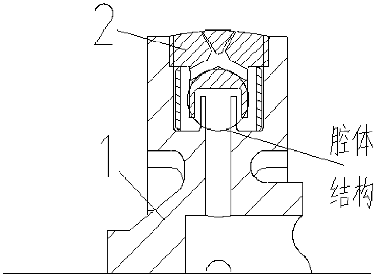
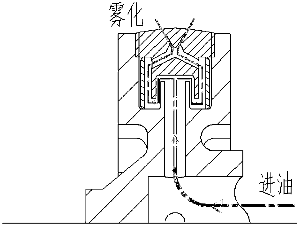
[0016] Such as figure 1 As shown, the present invention provides a wide cone angle atomization oil thrower structure, including the oil thrower body 1 and the nozzle 2; the oil thrower body 1 and the nozzle 2 are connected together by threaded connection, each The nozzle 2 is connected to the rotating shaft of the oil thrower body 1 by means of threaded connection. The oil thrower body 1 is provided with four internal threads, corresponding to the positions of the external threads of the four nozzles 2 distributed at intervals of 90° in the circumferential direction. The flow pipeline in the nozzle 2 and the flow pipeline in the oil slinger body 1 form a cavity structure; each nozzle 2 is provided with a plurality of i...


PUM


Abstract

The invention relates to a wide cone angle atomizing oil throwing disc structure, and relates to the technical field of turbine engines. According to the wide cone angle atomizing oil throwing disc structure, the design of spraying holes in the nozzles and the design of a cavity formed between an oil throwing disc body and the nozzles are adopted so that the good atomization effect can be obtainedat the lower rotating speed of the engine while the small turbine engine has the characteristic of being compact in structure, meanwhile, certain taper angle distribution can be guaranteed, the uniformity of the temperature field in a flame tube is improved, and the oil supply pressure is reduced; according to the wide cone angle atomizing oil throwing disc structure, the wide airspace work of the engine can be supported, namely, under different oil supply flows, atomized particle size distribution can be ensured by the oil throwing disc so that efficiently and stably burning in a combustionchamber can be ensured.

Description

technical field [0001] The invention relates to the technical field of turbine engines, in particular to a structure of a wide cone angle atomizing oil flinger. Background technique [0002] The currently used oil throwing pan mostly adopts two rows of holes or a single row of holes as the outlet for the fuel to enter the combustion chamber from the oil throwing pan. The existing centrifugal oil thrower throws oil out of discrete circular holes, and the size of the holes generally exceeds 0.4mm, which is relatively large, which easily leads to uneven oil supply in the flame tube, thus causing high temperature points in the flame tube , affecting the uniformity of the temperature field in the flame cylinder. In addition, the single-row hole outlet method is difficult to adapt to the engine form with a wide range of oil supply flow. Contents of the invention [0003] (1) Technical problems to be solved [0004] The technical problem to be solved by the present invention i...

Claims


Application Information

Patent Timeline
Patent Type & Authority Patents(China)
IPC IPC(8): F02C7/22
Inventor 蔡文哲李峰杨凯王大磊马同玲
Owner BEIJING POWER MACHINERY INST
Learn More