Supercharge Your Innovation With Domain-Expert AI Agents!

Flow detection device

A flow detection device and flow technology, applied in the direction of measuring device, liquid/fluid solid measurement, measurement capacity, etc., can solve the problems that the detection sensor cannot be subjected to instantaneous impact force, the detection sensor cannot adjust the height, etc., and achieves simple structure and convenient adjustment , Ease of use

Active Publication Date: 2018-06-12
MAANSHAN SHENHUA INSTR
View PDF6 Cites 2 Cited by
  • Summary
  • Abstract
  • Description
  • Claims
  • Application Information

AI Technical Summary

Problems solved by technology

[0005] The purpose of the present invention is to solve the problem in the prior art that the detection sensor cannot adjust the height and detect the flow of different water layers and the detection sensor cannot be subjected to the instantaneous impact force, and proposes a flow detection device

Method used


Image

  • Flow detection device
  • Flow detection device
  • Flow detection device

Examples


Embodiment 1

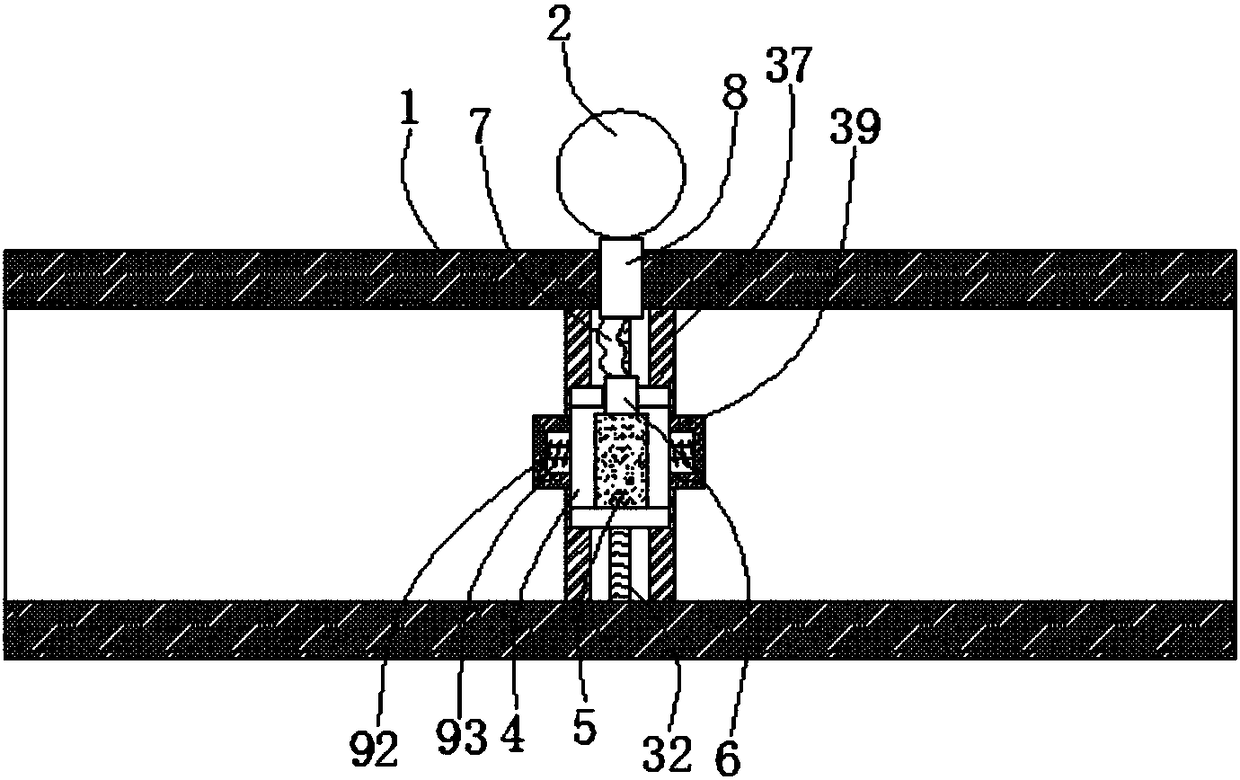
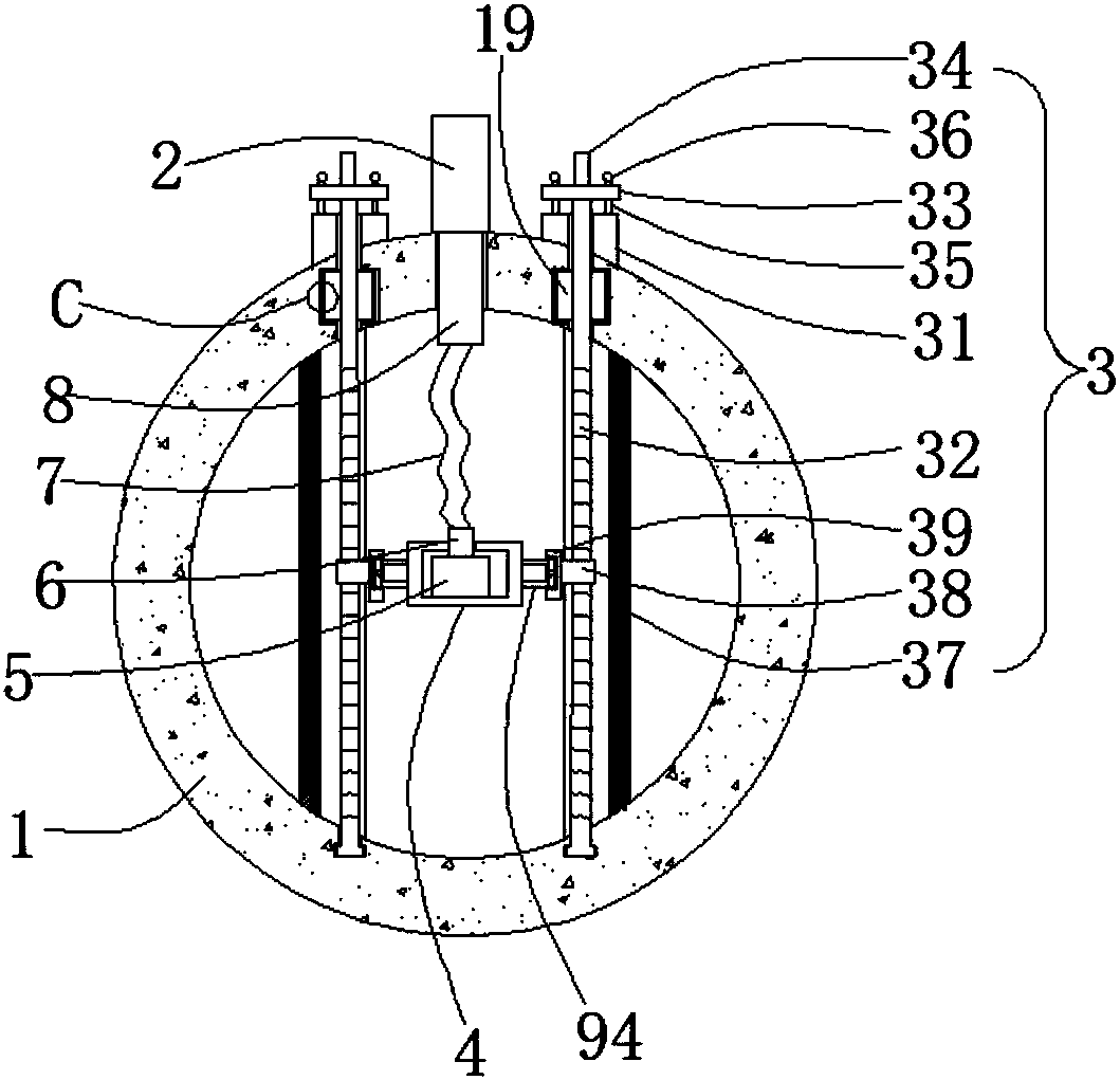
[0023] Embodiment 1: refer to Figure 1-4 , a flow detection device, comprising a fixed pipe 1, a flow detector 2 is fixedly connected to the fixed pipe 1, an adjustment mechanism 3 is fixedly connected to the fixed pipe 1, and the adjustment mechanism 3 includes two connecting blocks 31 fixed on the fixed ring 1 , the connecting block 31 is rotatably connected with a threaded rod 32, and the fixed ring 1 is fixedly connected with a guide plate 37 corresponding to the threaded rod 32. The guide plate 37 is arranged in a prism, and the guide plate 37 is provided with a receiving groove corresponding to the threaded rod 32. , the bottom of the threaded rod 32 runs through the connecting block 31 and the fixed pipe 1 in turn and is connected with the inner side wall of the fixed pipe 1 in rotation. The top of the rod 32 is fixedly connected with a turntable 33, the turntable 33 is fixedly connected with a first handle 34, the turntable 33 is inserted with a plurality of insertion...

Embodiment 2

[0026] Embodiment 2: refer to Figure 2-7 , applying the present invention to a field flow detection device, including a fixed pipe 1, a flow detector 2 is fixedly connected to the fixed pipe 1, and an adjustment mechanism 3 is fixedly connected to the fixed pipe 1, and the adjustment mechanism 3 includes a fixed ring 1 There are two connecting blocks 31, the connecting block 31 is rotatably connected with a threaded rod 32, the fixed ring 1 is fixedly connected with a guide plate 37 corresponding to the threaded rod 32, the guide plate 37 is arranged in a prism, and the guide plate 37 is provided with a screw thread. The receiving groove corresponding to the rod 32, the bottom of the threaded rod 32 runs through the connecting block 31 and the fixed pipe 1 in turn and is connected to the inner side wall of the fixed pipe 1 in rotation, the threaded rod 32 is threaded with a movable block 38, and the movable block 38 is fixedly connected There is a connecting plate 39, the top...


PUM


Abstract

The invention discloses a flow detection device. The device comprises a fixing pipe, a flow detector is fixedly connected to the fixing pipe, and an adjustment mechanism is fixedly connected to the fixing pipe; a mounting frame is arranged in the fixing pipe and connected with the adjustment mechanism through a buffer mechanism, a detection sensor is fixedly connected into the mounting frame, anda first rigid pipe is fixedly connected to the detection sensor; the top of the first rigid pipe penetrates through the top of the mounting frame and is fixedly connected with a hose, a second rigid pipe is fixedly connected to the top of the hose, the top of the second rigid pipe penetrates through the fixing pipe and is connected with the flow detector, and the second rigid pipe is fixedly connected with the fixing pipe through sealing. The flow detection device is simple in structure and convenient to operate, the instantaneous impact force of a flow sensor is reduced through the buffer mechanism, the work of the flow sensor is guaranteed accordingly, the height of the flow sensor is conveniently adjusted through the adjustment mechanism, then the flow condition of all layers of liquidis detected conveniently, and accordingly people use the device conveniently.

Description

technical field [0001] The invention relates to the technical field of flow detection devices, in particular to a flow detection device. Background technique [0002] At present, flow detection is required in some pipelines and open channels, so that people can make effective adjustments according to the flow situation, thereby preventing the overflow and rise of water flow. Automatic monitoring equipment for measurement and display, and storage. Real-time local display and automatic storage of measurement data. [0003] At present, the flow detector for flow detection on the pipeline detects the water flow in the pipeline through the detection sensor, but the detection sensor needs to be adjusted according to the water layer when used, otherwise it can only detect the flow of the same water layer in the pipeline Condition. The detection sensor is a sensitive element, so it cannot be subjected to an instantaneous excessive impact force. [0004] To this end, we have desi...

Claims


Application Information

Patent Timeline
Patent Type & Authority Applications(China)
IPC IPC(8): G01F15/10G01F15/18
CPCG01F15/105G01F15/185
Inventor 杨启凌
Owner MAANSHAN SHENHUA INSTR
Features
  • R&D
  • Intellectual Property
  • Life Sciences
  • Materials
  • Tech Scout
  • Unparalleled Data Quality
  • Higher Quality Content
  • 60% Fewer Hallucinations
Learn More