Display module particle detection camera mechanism

A particle detection and display module technology, applied in measuring devices, material analysis through optical means, instruments, etc., can solve the problems of low image quality, image instability, high power consumption, etc., and achieve high image quality and structure The effect of compactness and power reduction

Inactive Publication Date: 2018-06-12
DALIAN YISHENGDA INTELLIGENT TECH
View PDF6 Cites 1 Cited by
  • Summary
  • Abstract
  • Description
  • Claims
  • Application Information

AI Technical Summary

Problems solved by technology

[0003] The prior art display module particle detection camera has a complex structure and high power consumption, and cannot adapt to different applications and precision requirements. It cannot perform two different detections on the display module at the same time, and the detection efficiency is low. The scanned image Unstable, the image quality is not high, and it will have a negative impact on the particle detection results of the display module

Method used


Image

  • Display module particle detection camera mechanism
  • Display module particle detection camera mechanism
  • Display module particle detection camera mechanism

Examples


Embodiment approach 1

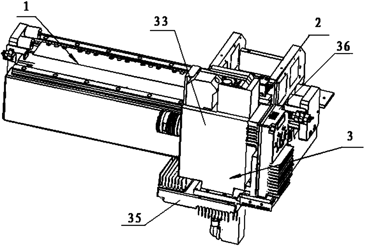
[0023] attached figure 1 It is a structural schematic diagram of a particle detection camera mechanism of a display module of the present invention.

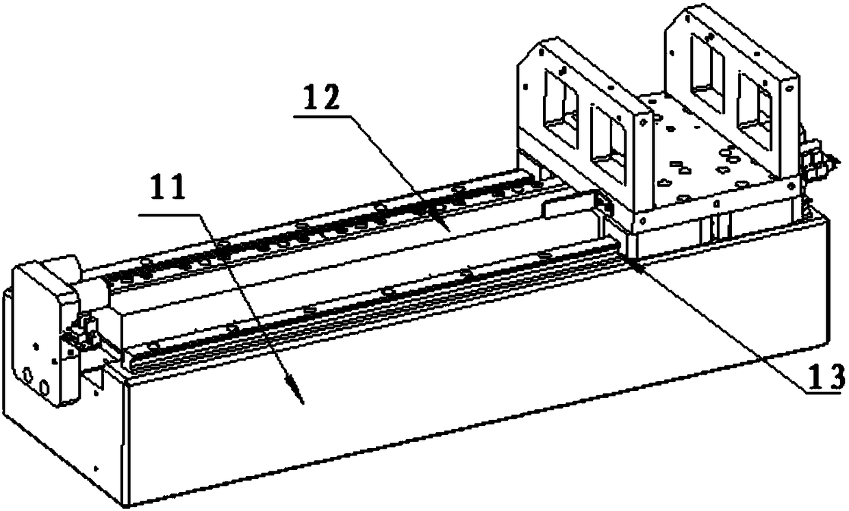
[0024] attached figure 2 It is a structural schematic diagram of a driving device 1 of a particle detection camera mechanism of a display module of the present invention.

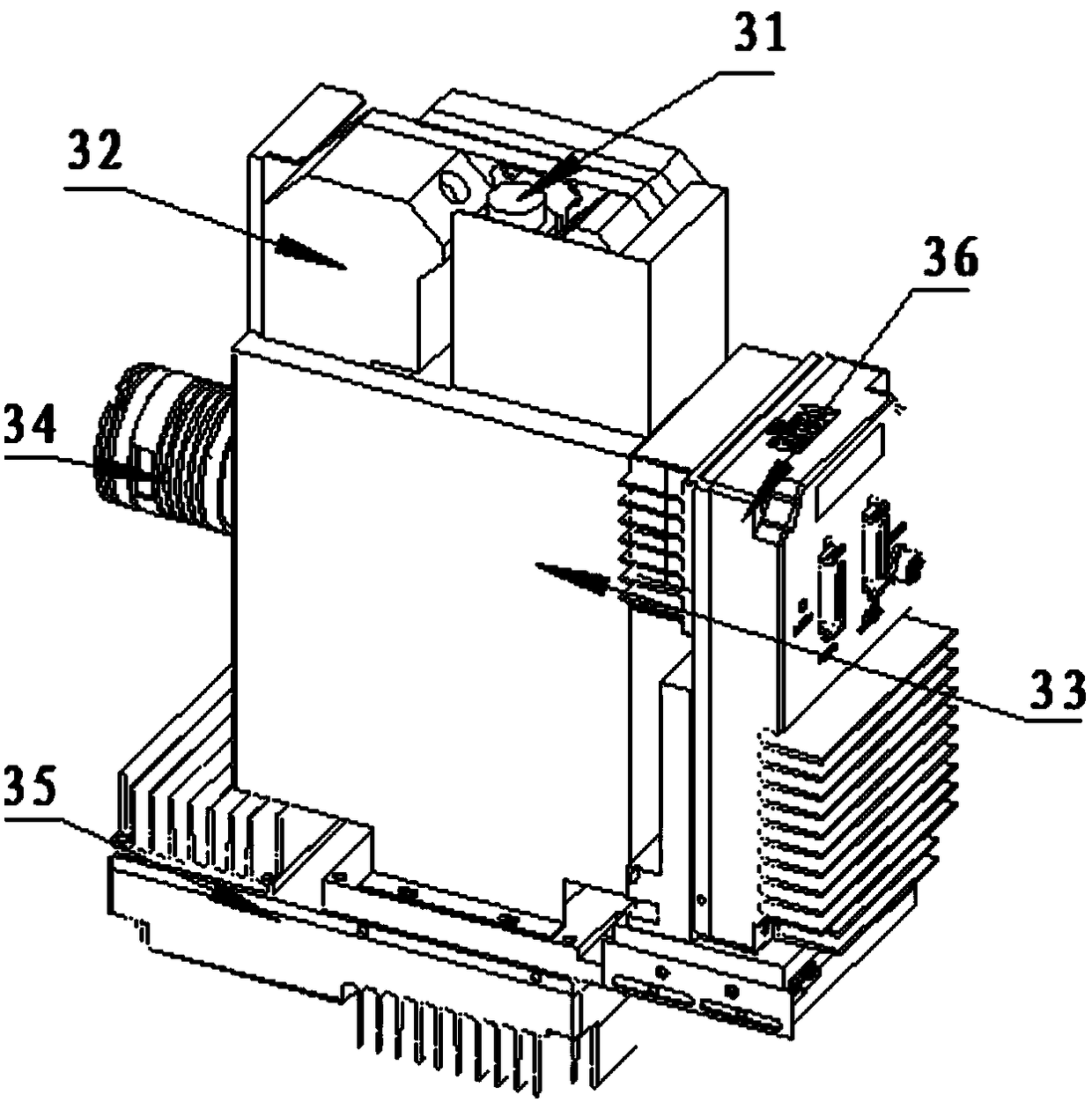
[0025] attached image 3 It is a structural schematic diagram of a detection camera device showing a module particle detection camera mechanism of the present invention.

[0026] A display module particle detection camera mechanism, characterized in that it includes:

[0027] Drive device one 1, drive device two 2, detection camera device 3,

[0028] Wherein: the first driving device 1 is slidingly connected to the second driving device 2, and the second driving device 2 is slidingly connected to the detection camera device 3;

[0029] The driving device-1 comprises: a base 11, a guide rail 12, a linear motor 13, and a linear encoder, wherein: the base ...

Embodiment approach 2

[0041] attached figure 1 It is a structural schematic diagram of a particle detection camera mechanism of a display module of the present invention.

[0042] attached figure 2 It is a structural schematic diagram of a driving device 1 of a particle detection camera mechanism of a display module of the present invention.

[0043] attached image 3 It is a structural schematic diagram of a detection camera device showing a module particle detection camera mechanism of the present invention.

[0044] A display module particle detection camera mechanism, characterized in that it includes:

[0045] Drive device one 1, drive device two 2, detection camera device 3,

[0046] Wherein: the first driving device 1 is slidingly connected to the second driving device 2, and the second driving device 2 is slidingly connected to the detection camera device 3;

[0047] The driving device-1 comprises: a base 11, a guide rail 12, a linear motor 13, and a linear encoder, wherein: the base ...


PUM


Abstract

The invention discloses a display module particle detection camera mechanism, which relates to a detection camera mechanism, in particular to a display module particle detection camera mechanism. Thedisplay module particle detection camera mechanism is characterized by comprising a driving apparatus I (1), a driving apparatus II (2) and a detection camera apparatus (3), wherein the detection camera apparatus (3) comprises a lens (31), a laser displacement sensor (32), a lens cone (33), light source (34), a main camera (35) and an auxiliary camera (36). Compared with the prior art, the displaymodule particle detection camera mechanism adopts the main camera and the auxiliary camera to share one lens cone, so that two different items of a display module can be simultaneously detected, thedetection efficiency is increased, the structure is compact, the weight is light, the power of a driving portion is reduced, the energy consumption is reduced, a scanned image is more stable, and theimage quality is higher.

Description

technical field [0001] The invention relates to a detection platform mechanism, in particular to a display module particle detection camera mechanism. Background technique [0002] With the development of technology, simple and cumbersome manual detection methods are gradually replaced by automatic detection equipment, and in order to ensure the detection accuracy of the detection machine, it is necessary to minimize the influence of external factors on the detection results, which is inseparable Open a display module particle detection camera mechanism with high precision, stable operation, more stable scanned images, and higher image quality. [0003] The particle detection camera of the prior art display module has a complex structure and high power consumption, and cannot adapt to different applications and precision requirements. It cannot perform two different detections on the display module at the same time, and the detection efficiency is low. The scanned image Uns...

Claims


Application Information

Patent Timeline
Patent Type & Authority Applications(China)
IPC IPC(8): G01N21/84
CPCG01N21/84
Inventor 李忠奎邹艳秋
Owner DALIAN YISHENGDA INTELLIGENT TECH
Why Eureka
Try Eureka