Target block fusion based moving target detection method

A moving target and detection method technology, applied in the field of image processing, can solve the problem that differential noise cannot obtain moving targets, etc., and achieve the effect of easy tracking and identification, simple and effective method

Active Publication Date: 2018-06-12
LUOYANG INST OF ELECTRO OPTICAL EQUIP OF AVIC
View PDF9 Cites 3 Cited by
  • Summary
  • Abstract
  • Description
  • Claims
  • Application Information

AI Technical Summary

Problems solved by technology

[0004] The purpose of the present invention is to provide a moving target detection method based on target block fusion, which is used to solve the problems of differential noise and inability to obtain a complete moving target in the prior art method

Method used


Image

  • Target block fusion based moving target detection method
  • Target block fusion based moving target detection method
  • Target block fusion based moving target detection method

Examples


Embodiment Construction

[0020] The specific embodiment of the present invention will be further described below in conjunction with accompanying drawing:

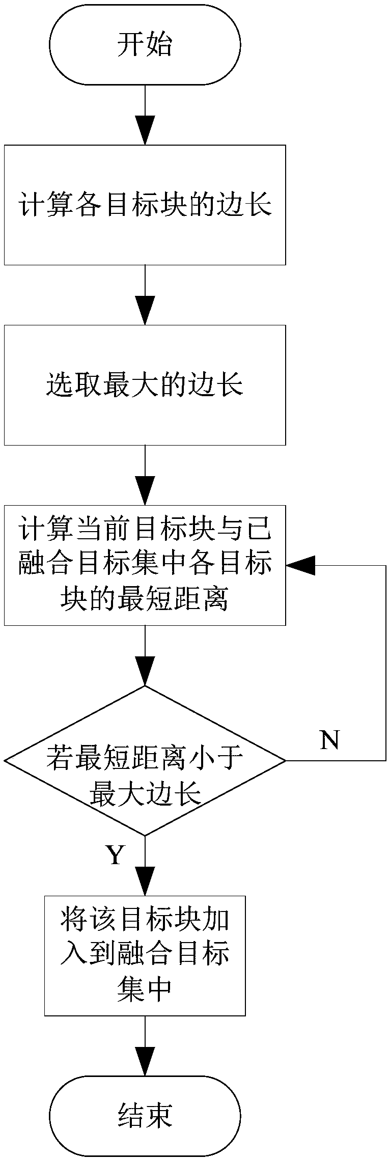
[0021] A moving target detection method based on target block fusion, such as image 3 shown, including the following steps:

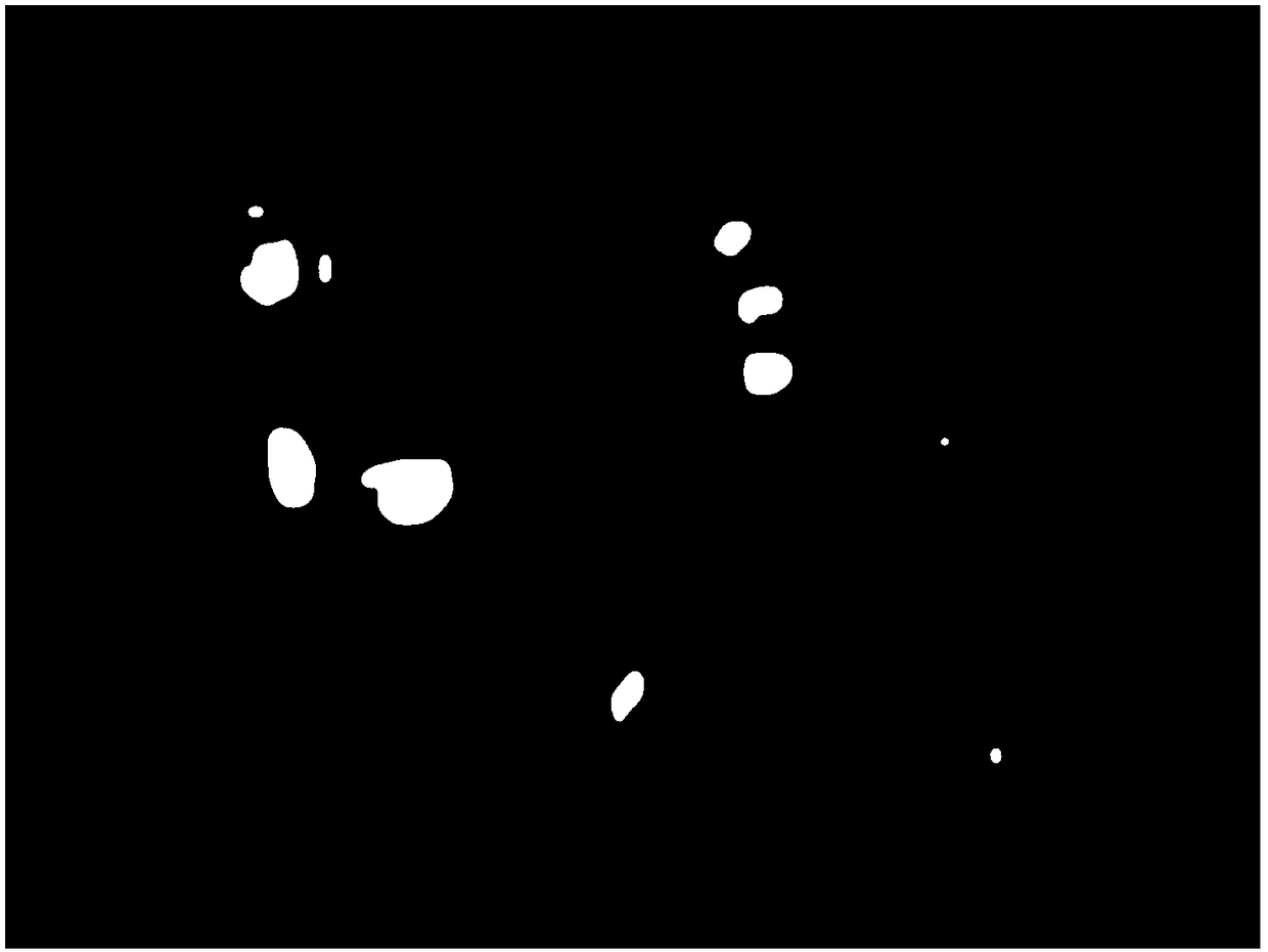
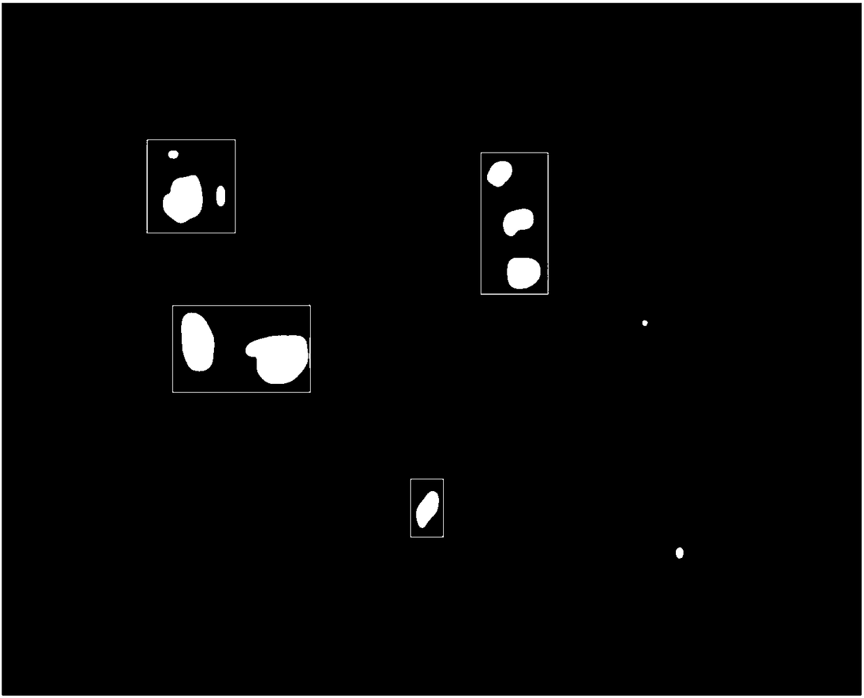
[0022] 1. Collect the video image of the moving target in the video sequence, and process the video image through image registration, image difference and threshold segmentation to obtain a binarized image. The moving target is usually identified by a non-continuous white area in the image, which is called a small target block set in this embodiment, such as figure 1 shown, denoted as b i ∈B (0≤i≤N, N is the number of small target blocks), for these small target blocks, before the fusion of small target blocks, it is first necessary to calculate the area of ​​each small target block, and determine the maximum area of ​​the target block and The minimum areas are denoted as objMaxarea and objMinarea respectively, and thei...


PUM


Abstract

The invention provides a target block fusion based moving target detection method. The method comprises the steps that the side length of each target block in a video image is calculated, and the maximal side length is recorded; a present target block is selected and fused, the distances from the present target block to all targets in a fused target set are calculated, and a minimal distance is recorded; if the minimal distance is lower than the maximal side length, the present target block is added to the target set; and other target blocks in the video image are fused till all the target blocks are fused, and a complete image of the moving target is obtained. The target blocks in the video image are fused continuously to obtain a complete and continuous moving target, convenience is provided for tracking and identification, and the method is simple and effective; and influence of differential noise can be removed, and a new moving target can be obtained by detection.

Description

technical field [0001] The invention belongs to the technical field of image processing, in particular to a moving target detection method based on target block fusion. Background technique [0002] For target detection in video, the usual method is to use the difference method, that is, two adjacent frames or multiple frames of images are directly subtracted after registration. After the registration, the relative position of the stationary object remains unchanged, but the position of the moving object changes, so there are traces of the moving object in the difference image, and then the moving target area can be extracted after threshold segmentation. [0003] Although the difference method is widely used in moving objects, the moving objects obtained by using the difference method are discontinuous and incomplete. Although the difference method is an effective method to extract moving targets, the moving target area obtained by it is usually discontinuous, that is, a s...

Claims


Application Information

Patent Timeline
Patent Type & Authority Applications(China)
IPC IPC(8): G06T7/223
CPCG06T2207/10016G06T7/223
Inventor 陈水忠邓秋平董博宇
Owner LUOYANG INST OF ELECTRO OPTICAL EQUIP OF AVIC
Why Eureka
Try Eureka