Multi-functional rain shielding paragliding paramotor

A flying umbrella and multi-functional technology, applied in the field of aircraft, can solve the problems of inability to hold an umbrella, inconvenient to carry, fixed umbrella surface area, etc., and achieve the effects of being convenient to manufacture, small and beautiful in appearance, and small in overall structure

Pending Publication Date: 2018-06-15
黄俊杰
View PDF5 Cites 0 Cited by
  • Summary
  • Abstract
  • Description
  • Claims
  • Application Information

AI Technical Summary

Problems solved by technology

[0002] At present, in people's lives, umbrellas are already inseparable. When people want to go out with umbrellas, ordinary umbrellas are generally larger in size and difficult to carry with them after folding; on rainy days, when people have more things on hand, Then there is no way to hold an umbrella, which is very inconvenient
Subsequently, just a lot of paragliders came out, but the existing paragliders also have umbrella surfaces, which are relatively large in size and inconvenient to carry. If you want to keep the position above the head of the person suspended, the control method is complicated and the relative cost is relatively high. The area of ​​the umbrella surface of the existing flying umbrella is fixed, which limits the range of rain protection. Generally, it is only suitable for one person. Even if you take too many things, you can't completely cover them.

Method used


Image

  • Multi-functional rain shielding paragliding paramotor
  • Multi-functional rain shielding paragliding paramotor
  • Multi-functional rain shielding paragliding paramotor

Examples


Embodiment Construction

[0021] The implementation of the present invention will be illustrated by specific specific examples below, and those skilled in the art can easily understand other advantages and effects of the present invention from the contents disclosed in this specification.

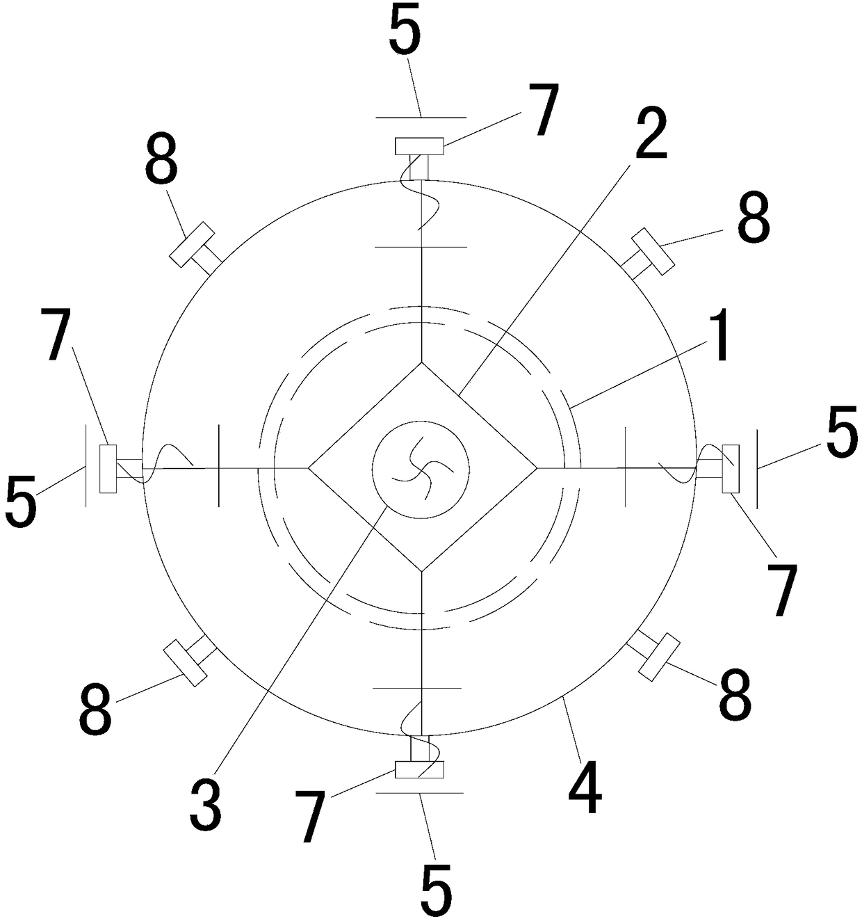
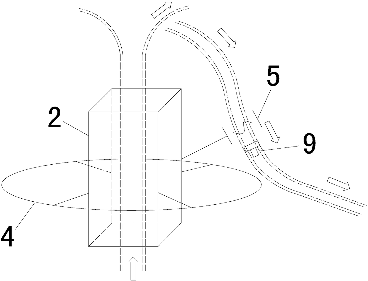
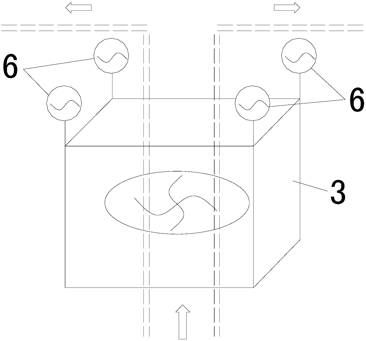
[0022] see Figure 1~Figure 3 . It should be noted that the structures, proportions, sizes, etc. shown in the drawings attached to this specification are only used to match the content disclosed in the specification, for those who are familiar with this technology to understand and read, and are not used to limit the implementation of the present invention. Limiting conditions, so there is no technical substantive meaning, any modification of structure, change of proportional relationship or adjustment of size, without affecting the effect and purpose of the present invention, should still fall within the scope of the present invention. The disclosed technical content must be within the scope covered. At the same ...


PUM


Abstract

Provided is a multi-functional rain shielding paragliding paramotor. The multi-functional rain shielding paragliding paramotor comprises a control module and a through paragliding paramotor body vertically arranged, a blower device is arranged in the paragliding paramotor body, the upper portion of the blower device is equispacedly provided with a plurality of first rotation type transponders, a rotary central axis of each first rotation type transponder is arranged at an certain angle with the vertical direction, the paragliding paramotor body penetrates through the middle portion of an annular guide plate formed by a plurality of annular sector guide plates, the periphery of the annular guide plate is equispacedly provided with a plurality of second rotation type transponders and third rotation type transponders which are used for changing airflow directions, the second rotation type transponders and the third rotation type transponders are arranged at an interval, the periphery ofthe paragliding paramotor body is further provided with a plurality of revolving wings uniformly distributed, fourth rotation type transponder used for changing airflow directions is arranged under each revolving wing, and the annular guide plate is arranged under each fourth rotation type transponder. The multi-functional rain shielding paragliding paramotor has the advantages that a rain shielding range can be controlled, the position of the paragliding paramotor is kept constant while the rain shielding range can be controlled, the structure is small, and the paragliding paramotor is convenient to carry.

Description

technical field [0001] The invention relates to an aircraft, in particular to a multifunctional rain-shielding flying umbrella. Background technique [0002] At present, in people's lives, umbrellas are already inseparable. When people want to go out with umbrellas, ordinary umbrellas are generally larger in size and difficult to carry with them after folding; on rainy days, when people have more things on hand, Then there is no way to hold an umbrella, which is very inconvenient. Subsequently, just a lot of paragliders came out, but the existing paragliders also have umbrella surfaces, which are relatively large in size and inconvenient to carry. If you want to keep the position above the head of the person suspended, the control method is complicated and the relative cost is relatively high. The area of ​​the umbrella surface of the existing flying umbrella is fixed, which limits the range of rain protection. Generally, it is only suitable for one person. Even if there a...

Claims


Application Information

Patent Timeline
Patent Type & Authority Applications(China)
IPC IPC(8): A45B11/00A45B25/00B64C39/02
CPCA45B11/00A45B25/00B64C39/02
Inventor 黄俊杰
Owner 黄俊杰
Why Eureka
Try Eureka