
Medical equipment pipeline cleaning device

A technology for cleaning devices and medical equipment, applied in the direction of cleaning hollow objects, cleaning methods and utensils, chemical instruments and methods, etc., can solve problems such as unfavorable assembly and operation, time-consuming and labor-intensive, limited cleaning capacity, etc., to reduce cleaning costs and increase Economic benefits, the effect of improving labor efficiency

Inactive Publication Date: 2018-06-15
HUNAN HUIXUN ENTERPRISE MANAGEMENT CO LTD
View PDF5 Cites 1 Cited by
  • Summary
  • Abstract
  • Description
  • Claims
  • Application Information

AI Technical Summary

Problems solved by technology

[0002] Hospitals and medical units in our country usually only scrub the outer surface of the medical instrument, and do not clean the internal pipeline of the instrument, which will seriously affect the service life of the medical equipment; in the prior art, the cleaning of the pipeline is a very troublesome task. Generally, the cleaning method can only be cleaned by rotating the brush head and flushing with large water flow. The supporting equipment is complicated, time-consuming and laborious, and the cleaning effect is often difficult to guarantee. Due to incomplete cleaning, it often causes silt after cleaning; In addition, ordinary pipeline cleaning devices are all fixed inclusions, without flexibility, flushing water will block the pipeline when cleaning the pipeline, and it is not conducive to assembly and operation, and the cleaning capacity is limited; therefore, we need a medical equipment pipeline cleaning device

Method used

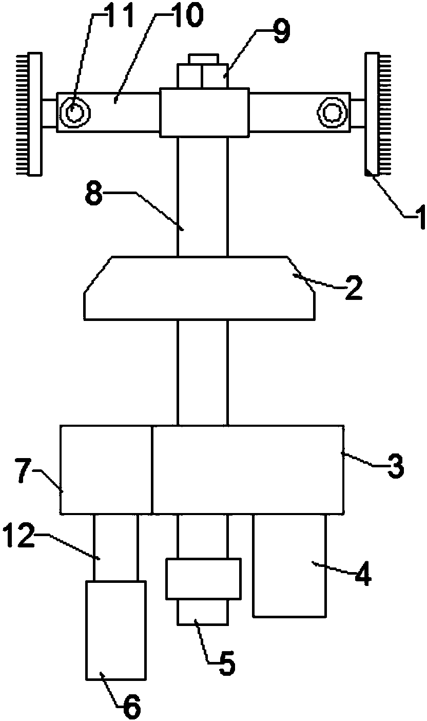
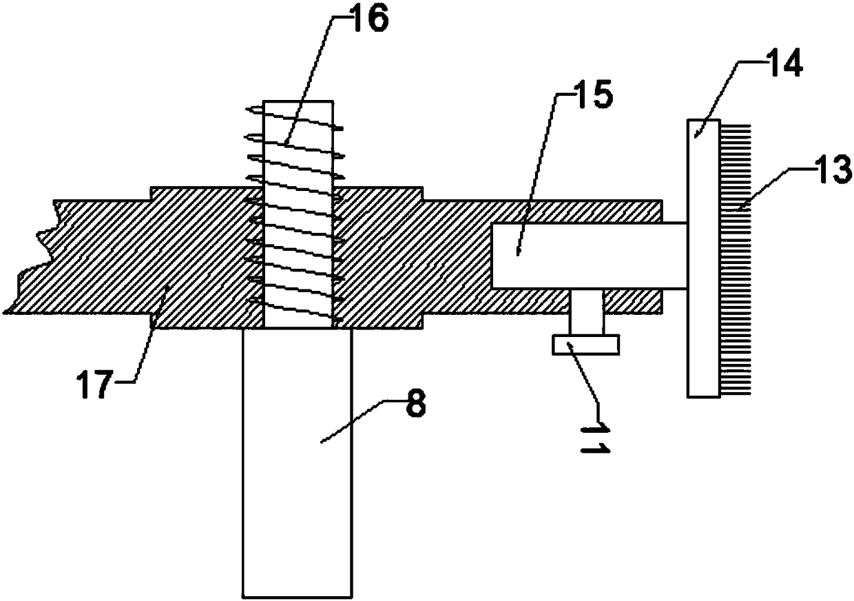
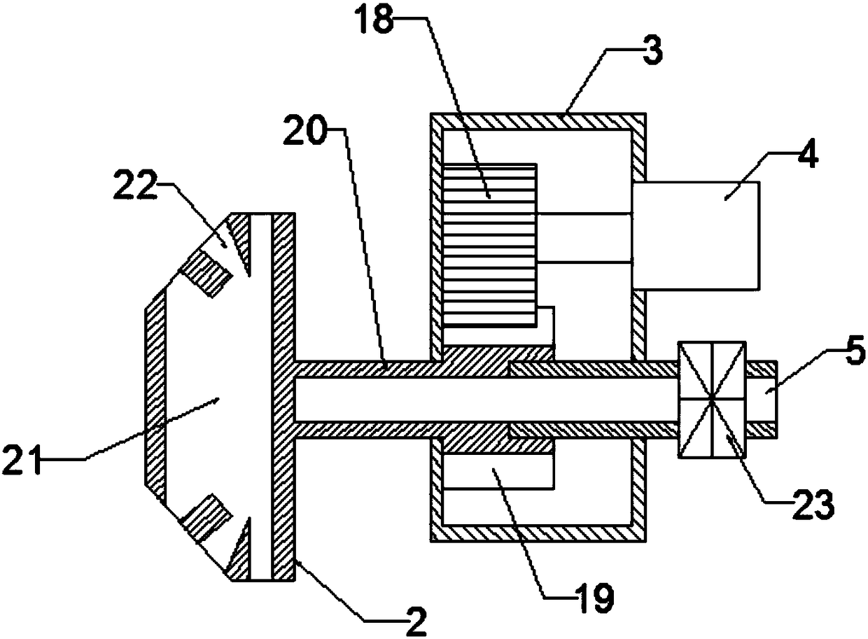

Image

  • Medical equipment pipeline cleaning device
  • Medical equipment pipeline cleaning device
  • Medical equipment pipeline cleaning device

Examples


Embodiment Construction

[0016] The technical solution of this patent will be further described in detail below in conjunction with specific embodiments.

[0017] Embodiments of the present patent are described in detail below, examples of which are shown in the drawings, wherein the same or similar reference numerals designate the same or similar elements or elements having the same or similar functions throughout. The embodiments described below by referring to the figures are exemplary and are only used for explaining the patent, and should not be construed as limiting the patent.

[0018] In the description of this patent, it is to be understood that the terms "center", "upper", "lower", "front", "rear", "left", "right", "vertical", "horizontal", The orientation or positional relationship indicated by "top", "bottom", "inner", "outer", etc. is based on the orientation or positional relationship shown in the drawings, and is only for the convenience of describing this patent and simplifying the des...


PUM


Abstract

The invention discloses a medical equipment pipeline cleaning device and belongs to the technical field of medical equipment maintenance. The medical equipment pipeline cleaning device comprises brushdevices, an installing disc, a spraying device and a telescopic device. The brush devices are arranged at one ends of sleeve rods. The brush devices comprise brushes and brush handles. The other endsof the sleeve rods are arranged in sleeves. The four arranged sleeves are fixedly connected with the installing disc. The sleeve rods are fixed to the sleeves through fastening screws. A bolt is arranged at one end of a fixed rod and is fixedly connected with the installing disc through mutual screwing of the bolt and a nut. A liquid inlet pipe is fixed to the side face of a transmission device and is further provided with a booster pump. According to the medical equipment pipeline cleaning device, a medical equipment pipeline is cleaned in the mode that high-rotation-speed friction cleaningand high-pressure spray cleaning are combined, the cleaning effect is good, meanwhile labor efficiency is improved, the amount of chemical cleaning fluid is reduced, cleaning cost is lowered, environmental protection pressure is avoided, and economic benefit is increased.

Description

technical field [0001] The invention relates to the technical field of medical equipment maintenance, in particular to a medical equipment pipeline cleaning device. Background technique [0002] Hospitals and medical units in our country usually only scrub the outer surface of the medical instrument, and do not clean the internal pipeline of the instrument, which will seriously affect the service life of the medical equipment; in the prior art, the cleaning of the pipeline is a very troublesome task. Generally, the cleaning method can only be cleaned by rotating the brush head and flushing with large water flow. The supporting equipment is complicated, time-consuming and laborious, and the cleaning effect is often difficult to guarantee. Due to incomplete cleaning, it often causes silt after cleaning; In addition, ordinary pipeline cleaning devices are all fixed inclusions, without flexibility, flushing water will block the pipeline when cleaning the pipeline, and it is not ...

Claims


Application Information

Patent Timeline
Patent Type & Authority Applications(China)
IPC IPC(8): B08B9/051
CPCB08B9/051
Inventor 金雄
Owner HUNAN HUIXUN ENTERPRISE MANAGEMENT CO LTD
Learn More