
Section steel anti-tilt tooling

A profile steel and anti-tilt technology, applied in auxiliary devices, manufacturing tools, metal processing equipment, etc., can solve problems such as damage to the outer surface of angle steel and lower work efficiency of support plates, and achieve the effects of weight reduction, convenient operation, and strong stability

Inactive Publication Date: 2018-06-15
SHANGHAI WAIGAOQIAO SHIP BUILDING CO LTD
View PDF8 Cites 1 Cited by
  • Summary
  • Abstract
  • Description
  • Claims
  • Application Information

AI Technical Summary

Problems solved by technology

[0004] The technical problem to be solved by the present invention is to provide a section steel anti-tilt tooling in order to overcome the defect that the welding and removal of the support plate in the prior art reduces work efficiency and damages the outer surface of the angle steel

Method used


Image

  • Section steel anti-tilt tooling
  • Section steel anti-tilt tooling
  • Section steel anti-tilt tooling

Examples


Embodiment 1

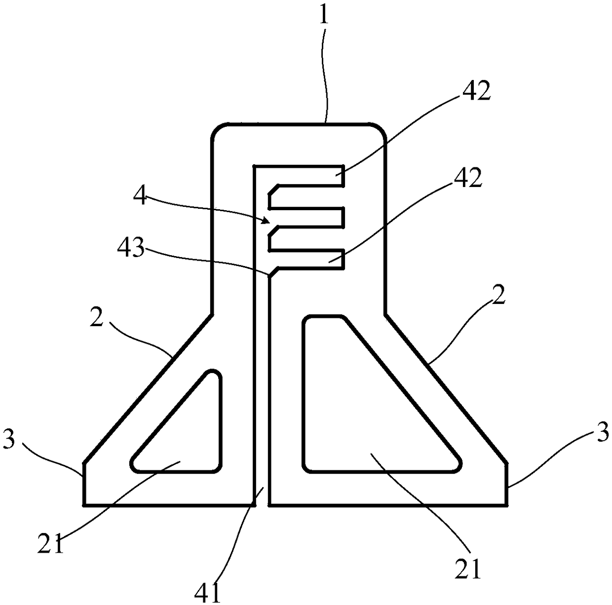
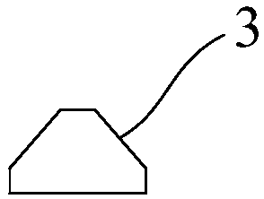
[0044] This embodiment provides a steel anti-tilt tooling, such as figure 1 As shown, the section steel anti-tilt tooling includes a vertical plate 1 , a support plate 2 and a foot 3 that can be erected.

[0045] The height direction of the riser 1 is kept perpendicular to the thickness direction of the riser 1, the riser 1 is provided with a receiving groove 4, the receiving groove runs through the riser 1 along the thickness direction of the riser 1, and the receiving groove 4 includes a first receiving groove 41 and The second accommodating groove 42, the first accommodating groove 41 extends upwards from the lower end of the riser 1, the second accommodating groove 42 and the first accommodating groove 41 are perpendicular to each other, and the second accommodating groove 42 and the first accommodating groove 41 are connected Yes, the second accommodating groove and the first accommodating groove form an L shape.

[0046] The accommodating groove 4 passes through one end...

Embodiment 2

[0057] This embodiment provides a profiled steel anti-tilt tooling, the structure of the profiled steel anti-tilt tooling of this embodiment is roughly similar to the structure of the profiled steel anti-tilt tooling of Embodiment 1, the difference is that, as Figure 4 As shown, the second accommodating groove and the first accommodating groove form a T shape. When applied to angle steel, the T-shaped structure does not need to consider the placement direction of the angle steel, and can also adapt to more types of steel, so the T-shaped structure is more adaptable than the L-shaped structure.


PUM


Abstract

The invention discloses a section steel anti-tilt tooling. The tooling comprises a vertical plate capable of vertically setting, accommodation grooves are formed in the vertical plate, the accommodation grooves penetrate through the vertical plate in the thickness direction of the vertical plate, the accommodation grooves comprise a first accommodation groove, the first accommodation groove extends upwards from the lower end face of the vertical plate, the accommodation grooves further comprise a second accommodation groove, the second accommodation groove is perpendicular to the first accommodation groove and communicated with the first accommodation groove, and the accommodation grooves are formed for the section steels to penetrate through to constrain the section steels from tilting. According to the tooling, by forming two accommodation grooves which are communicated with each other in the vertical plate capable of vertically setting, the section steels can conveniently penetratethrough the accommodation grooves from one end faces of the section steels in the length direction of the section steels, so that tilting of the section steels is constrained, after the operation is completed, the vertical plate can be taken away from the section steels conveniently, the tooling is movably connected with the section steels, operation time can be reduced, the working efficiency isimproved, and outer surfaces of angle steels are not damaged.

Description

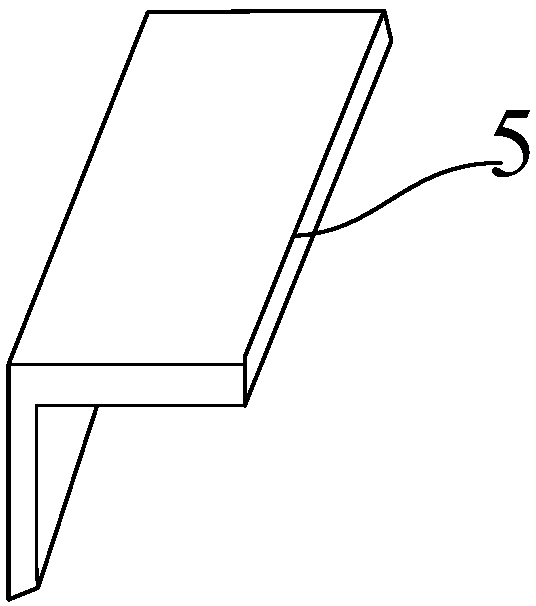
technical field [0001] The invention relates to a tool, in particular to a section steel anti-tilt tool. Background technique [0002] In the fields of machinery manufacturing and shipbuilding, angle steel is a very widely used section steel. Angle steel is mainly used as a frame structure, and other operations will be performed on the angle steel, such as welding operations. When welding, it is often necessary to erect one wide side of the angle steel , to operate on the other wide side, in order to prevent the angle steel from toppling over, it is necessary to support the angle steel. [0003] In the prior art, the support plate is first welded on the other wide side to form a support between the support plate and the ground, and the support plate is removed after the operation is completed. This method will increase the operating time additionally, reduce the work efficiency, and also damage the outer surface of the angle steel. Contents of the invention [0004] The ...

Claims


Application Information

Patent Timeline
IPC IPC(8): B23K37/04
Inventor 张理燕张文杰于春龙张海甬谢立荣
Owner SHANGHAI WAIGAOQIAO SHIP BUILDING CO LTD
Learn More