Lifting clamping mechanism for car gear shaft maintenance

A clamping mechanism and gear shaft technology, applied in the direction of lifting frame, workpiece clamping device, lifting device, etc., can solve the problems of easy sliding, low efficiency, low clamping firmness, etc., and achieve convenient maintenance and firm clamping and fixing. Effect

Inactive Publication Date: 2018-06-15
FOSHAN HUAPU RUILIAN ELECTROMECHANICAL TECH CO LTD
View PDF0 Cites 9 Cited by
  • Summary
  • Abstract
  • Description
  • Claims
  • Application Information

AI Technical Summary

Problems solved by technology

[0002] When the gear shaft and other parts inside the existing automobile are processed, it is generally necessary to manually fix the bolts with the clamping block, which has low efficiency, and the clamping degree is not high, and it is easy to slide

Method used


Image

  • Lifting clamping mechanism for car gear shaft maintenance
  • Lifting clamping mechanism for car gear shaft maintenance

Examples


Embodiment

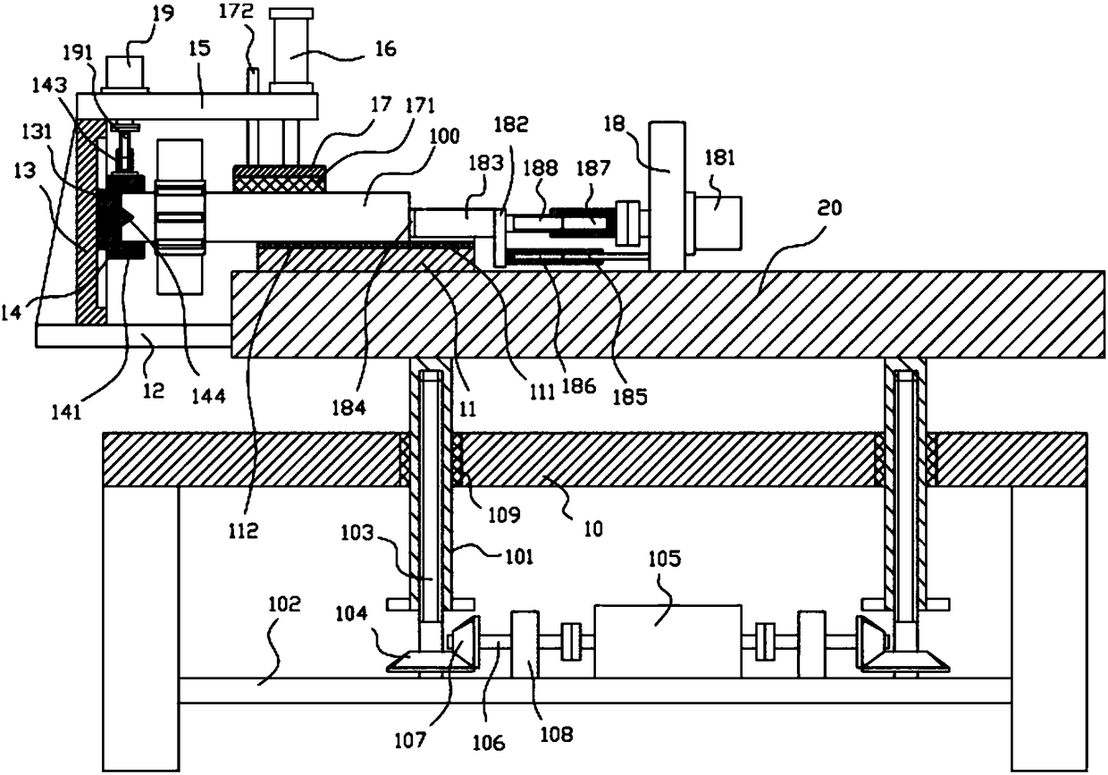
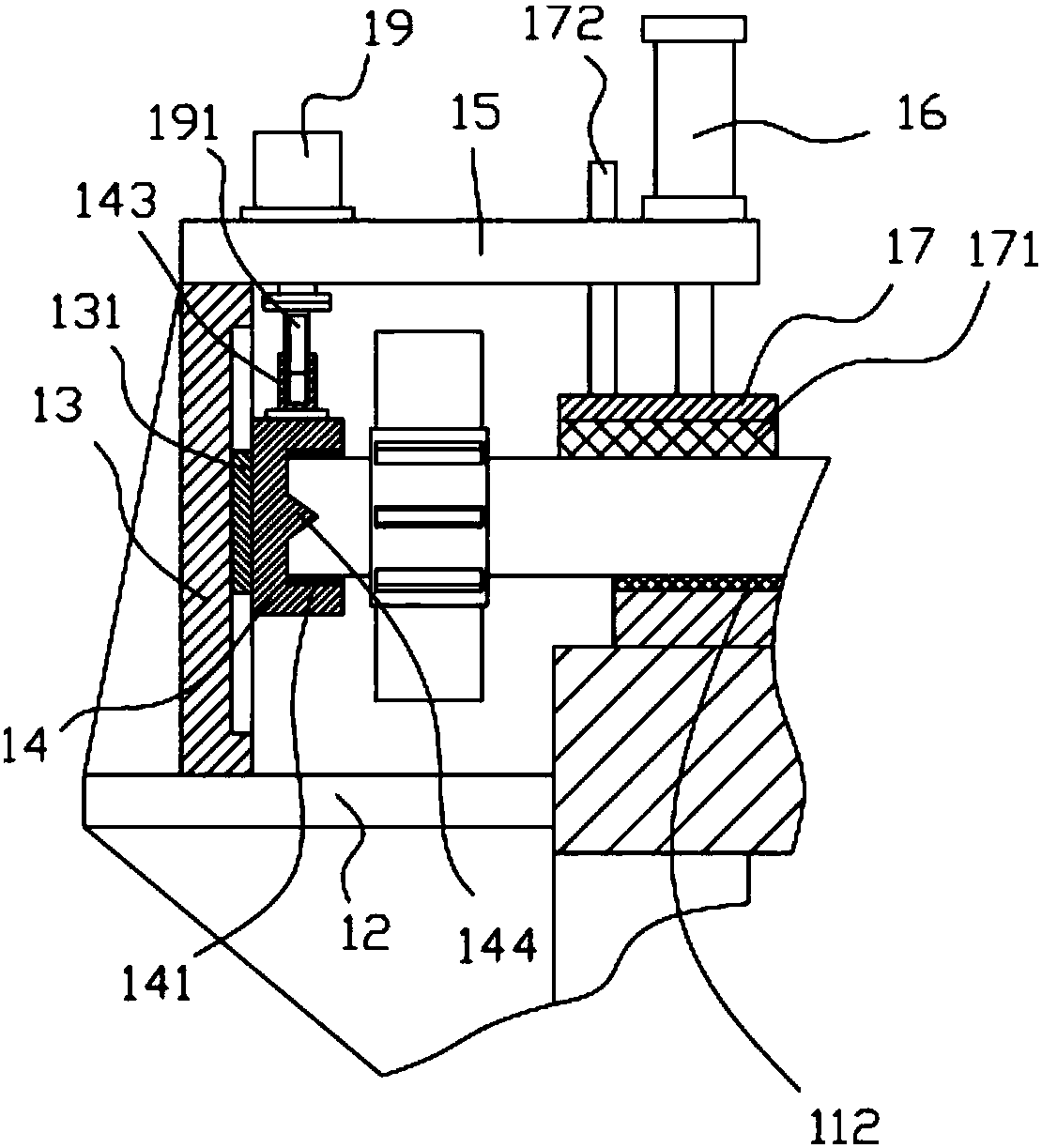
[0021] Example: see Figure 1 to Figure 2 As shown, a lifting clamping mechanism for automobile gear shaft maintenance includes a frame 10 and a lifting main board 20. The lifting main board 20 is located above the top plate of the frame 10, and the top plate of the frame 10 has two vertical inserts. Straight adjustment screw sleeve 101, the top end of the vertical adjustment screw sleeve 101 protrudes from the top surface of the top plate of the frame 10 and is fixed on the bottom surface of the lifting main board 20, and the lower horizontal fixing plate is fixed on the lower side wall of the leg of the frame 10 102. Both sides of the top surface of the lower horizontal fixing plate 102 are hinged with lifting vertical screws 103, the upper part of the lifting vertical screw 103 is screwed in the vertical adjustment screw sleeve 101, and the lower part of the vertical adjustment screw sleeve 101 is in the frame 10. Below the top plate of the vertical screw 103, a transmission...


PUM


Abstract

The invention discloses a lifting clamping mechanism for car gear shaft maintenance. The lifting clamping mechanism includes a machine frame and a lifting main plate, the lifting main plate is locatedabove a top plate of the machine frame, and two vertical regulating threaded sleeves are inserted in the top plate of the machine frame in a sleeving mode; the top ends of the vertical regulating threaded sleeves extend out of the top surface of the top plate of the machine frame to be fixed to the bottom surface of the lifting main plate, the lower side wall of support legs of the machine frameis fixedly provided with a lower horizontal fixing plate, and lifting vertical screws are hinged to two sides of the top surface of the horizontal fixing plate; the upper portions of the lifting vertical screws are in screw joint with the vertical regulating threaded sleeves, the lower portions of the vertical regulating threaded sleeves are located below the top plate of the machine frame, and the lower portions of the lifting vertical screws are fixedly provided with transmission bevel gears; and the middle portion of the top surface of the lower horizontal fixing plate is fixedly provided with a two-output-shaft motor, two output shafts of the two-output-shaft motor are connected with transition shafts through couplings, and the end portions of the transition shafts are fixedly providedwith the driving bevel gears. According to the lifting clamping mechanism for the car gear shaft maintenance, a gear shaft can be clamped and fixed and can perform high-low position regulation according to the need, the clamping and the fixing are firm, and the maintenance is convenient.

Description

Technical field: [0001] The invention relates to the technical field of automobile parts manufacturing equipment, and more specifically to a liftable clamping mechanism for automobile gear shaft maintenance. Background technique: [0002] When processing parts such as gear shafts in existing automobiles, it is generally necessary to manually use clamping blocks for bolt fixing, which has low efficiency, low clamping firmness, and easy sliding. Summary of the invention: [0003] The purpose of the present invention is to address the shortcomings of the prior art, and provide a lifting clamping mechanism for automobile gear shaft maintenance, which can automatically clamp and fix the gear shaft and adjust the height according to needs, and the clamping and fixing is firm, Easy to maintain. [0004] The technical solutions of the present invention are as follows: [0005] A lifting clamping mechanism for automobile gear shaft maintenance, comprising a frame and a lifting main board. Th...

Claims


Application Information

Patent Timeline
IPC IPC(8): B25B11/00B25H1/06B25H1/08B25H1/16B66F7/14B66F7/28
CPCB25B11/00B25H1/06B25H1/08B25H1/16B66F7/14B66F7/28
Inventor 付主枝
Owner FOSHAN HUAPU RUILIAN ELECTROMECHANICAL TECH CO LTD
Why Eureka
Try Eureka