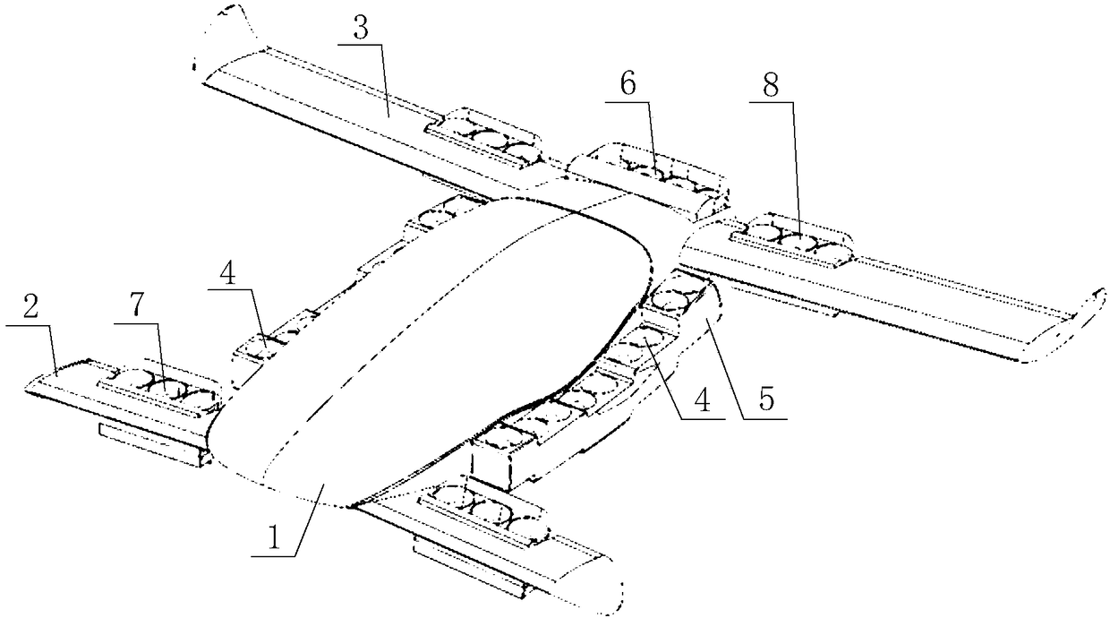
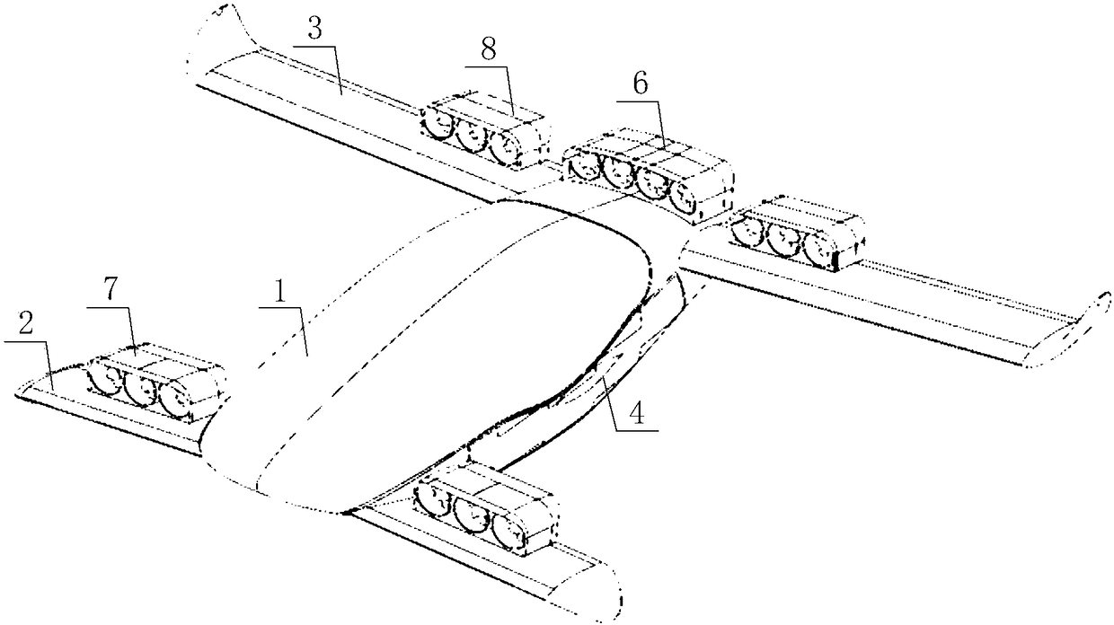
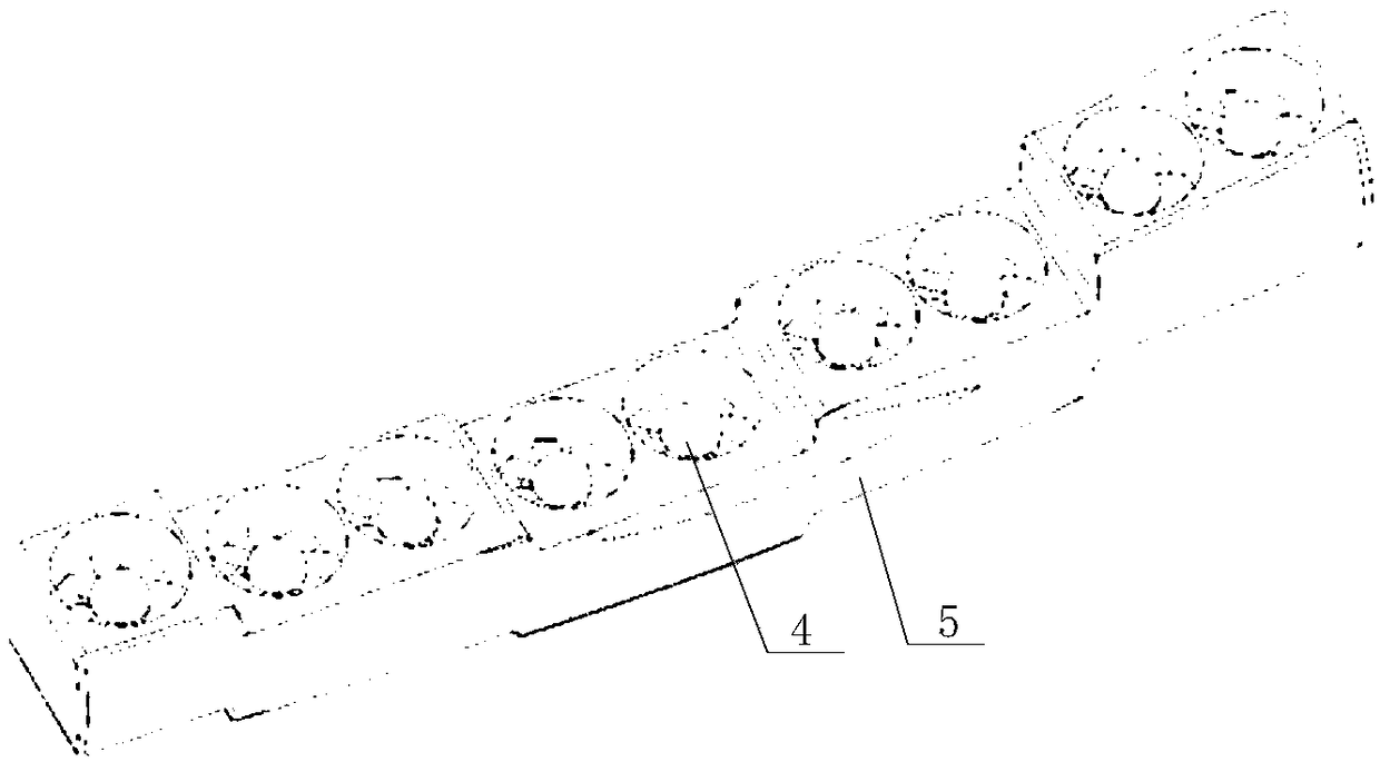
[0024] The core of the present invention is to provide an aircraft with improved overall performance, which is specifically manifested as having better level flight performance and vertical take-off and landing performance at the same time.
[0025] In order to enable those skilled in the art to better understand the technical solutions of the present invention, the present invention will be further described in detail below with reference to the accompanying drawings and embodiments.
[0026] Please refer to Figure 1 to Figure 4 In a specific embodiment, the aircraft provided in the specific embodiment of the present invention includes a fuselage body 1, two front wings 2 symmetrically arranged at the head of the fuselage body 1, and two symmetrically arranged at the tail of the fuselage body 1. The main wing 3, the front wing 2 are the lower single wing, the main wing 3 is the upper single wing, the root tip ratio of the main wing 3 and the front wing 2 are both 1:1, and there is no sweep angle. Preferably, the front wing 2 and the main wing 3 are rectangular wings to obtain low-speed cruise ( <0.3 Mach), high aerodynamic efficiency, convenient for production and maintenance.
[0027] It can be seen from the above description that in the aircraft provided in the specific embodiment of this application, the wings adopt a front and rear double-wing layout to ensure sufficient area and reduce the demand for hangars and landing sites. The front wing 2 is the lower single wing, and the main wing 3 For the upper single wing, the upper single wing with the least interference resistance is selected for the main wing 3, while reducing the influence of the front wing 2 and the front engine wake on the wing, the root tip ratio of the main wing 3 and the front wing 2 are both 1:1, and There is no swept angle, which improves the aerodynamic efficiency of flight, and weighs the performance of horizontal flight and vertical take-off and landing, and is designed with higher horizontal flight performance and vertical take-off and landing performance.
[0028] Furthermore, the aircraft also includes a main wing ducted fan group 8, a front wing ducted fan group 7, and a fan for driving the main wing ducted fan group 8 to rotate as a whole and driving the front wing ducted fan group 7 to rotate as a whole to control the thrust vector. The control device, specifically, the main wing ducted fan group 8 and the front wing ducted fan group 7 can change the direction of the thrust vector by driving the overall rotation of an independent motor, and the motor is arranged on the fuselage body 1. The main wing ducted fan group 8 can be rotatably arranged at the wing root of the main wing 3, and the front wing ducted fan group 7 can be rotatably arranged at the wing root of the front wing 2. Further, preferably, the ducted fan arrangement direction on the main wing ducted fan group 8 is parallel to the length direction of the main wing 3, and the ducted fan arrangement direction on the front wing ducted fan group 7 is parallel to the length direction of the front wing 2. Specifically, the main wing ducted fan group 8 and the front wing ducted fan group 7 both include three ducted fans arranged in sequence. Specifically, the blade rotation center line of the ducted fan in the main wing ducted fan group 8 is perpendicular to the length direction of the main wing 3, and the main wing ducted fan group 8 is arranged behind the main wing 3. The blade rotation center line of the ducted fan in the front wing ducted fan group 7 is perpendicular to the length direction of the front wing 2, and the front wing ducted fan group 7 is arranged behind the front wing 2.
[0029] Further, the aircraft also includes a tail ducted fan group 6 rotatably arranged at the tail of the fuselage body 1, wherein the tail ducted fan group 6 can be driven by a motor to rotate as a whole to change the thrust vector direction. Preferably, the tail ducted fan group 6 is set at the rear of the tail of the fuselage body 1, the blade rotation center line of the ducted fan in the tail ducted fan group 6 is perpendicular to the width direction of the fuselage body 1, and the tail ducted fan group 6 is rotated by a fan control device. The ducted fan group 6 is located between the two main wing ducted fan groups 8, and the ducted fans on the tail fan group are arranged along the width direction of the fuselage body 1. Specifically, the ducted fan is a small ducted fan of 30 cm, and the maximum thrust of a single fan is 400N. Of course, ducted fans of different thrusts and sizes can be selected according to actual conditions in the actual design.
[0030] Furthermore, the aircraft also includes two side ducted fan groups 4, two side ducted fan groups 4, and the ducted fans of the two side ducted fan groups 4 are symmetrically arranged on the left and right sides of the fuselage body 1. On the side, the side ducted fan group 4 is controlled by the fan control device to translate. When the side ducted fan 4 is working, the fan control device controls the side ducted fan group 4 to move to the outside of the fuselage body 4 when it is in level flight. At this time, the fan control device controls the side ducted fan assembly 4 to move into the body 4 of the fuselage. The main wing ducted fan group 8 and the front wing ducted fan group 7 reduce its influence on the aerodynamic efficiency of the wing. And combined with the aileron/elevator to reduce the number of moving parts and reduce the complexity of the structure. The tail ducted fan group 6 is installed on the upper surface of the rear of the fuselage body 1, and the air inlet is close to the fuselage body 1, accelerating the boundary layer of the fuselage body 1, reducing the thickness of the boundary layer, thereby reducing friction resistance. The engine wake accelerates the low-speed airflow in the flying wake and reduces the shape resistance. Power layout, install the main wing ducted fan group 8 and the front wing ducted fan group 7 respectively on the wing root of the main wing 3 and the wing root of the front wing 2. The downwash airflow can be reduced by changing the ducted fan inlet and nozzle angles The negative impact on the wings.
[0031] Preferably, the tail ducted fan group 6 includes four ducted fans arranged in sequence. Preferably, the ducted fans of the tail ducted fan group 6 are arranged along the width direction of the fuselage body 1, and the side ducted fan group 4 includes nine ducted fans arranged in sequence. For the ducted fans to be arranged, the ducted fans of the side ducted fan group 4 are preferably arranged along the length direction of the fuselage body 1.
[0032] Further, the front wing 2 has a dihedral angle, and the end of the front wing 2 is provided with a winglet, which is turned down. The lower single wing is selected for the front wing 2 to ensure the vision of the cockpit and reduce the influence of airflow disturbance on the main wing 3. The dihedral angle causes the airflow to converge toward the belly, which can slightly improve the lift and aerodynamic efficiency of the fuselage. The winglet is folded downward to further reduce the position of the low pressure area of the wingtip vortex core and reduce its negative impact on the main wing 3. The counterclockwise rotating vortex generated by the front wing 2 causes the inner wing section of the main wing 3 to receive the downwash airflow, which causes the aerodynamic efficiency of the inner wing section of the main wing 3 to decrease and the induced drag increases. The outer wing section of the main wing 3 receives upwash airflow, which can increase the aerodynamic efficiency of the aircraft within a certain range and reduce the induced drag.
[0033] Preferably, the end of the main wing 3 is provided with a winglet. The dihedral angle raises the outer wing section of the main wing 3 to avoid contact with the low pressure area of the front wing 2 wingtip vortex core, and improve the roll stability. The outer wing section of the main wing 3 is not equipped with ducted fans, and winglets are added to maximize the efficiency improvement brought by the upwash airflow.
[0034] The aircraft provided in this application uses a total of 34 ducted fans to provide lift, and 16 ducted fans are installed on the upper surface of the tail and wing, namely the main wing ducted fan group 8, the front wing ducted fan Group 7 and tail ducted fan group 6 provide thrust in level flight, and tilt the nozzle downward to provide lift when hovering. The attitude control of the aircraft is achieved by changing the angle and thrust of these 16 ducted fans. 18 ducted fans are installed on both sides of the fuselage body 1, that is, the side ducted fan group 4, retracted in level flight to improve aerodynamic efficiency, and deployed when hovering. Because it is only used when hovering, the inlet and nozzle are designed to improve static thrust and energy efficiency. Except in extreme cases, the ducted fans of the side ducted fan group 4 do not participate in attitude control.
[0035] Preferably, the fuselage body 1 is provided with a liquid crystal display and a human-computer interaction touch screen, and the cockpit cover of the fuselage body 1 is a transparent cockpit cover. Through the LCD screen, the data presentation form is more flexible and clear. Through the touch screen operation, the difficulty of operation is reduced, and the human-computer interaction is smoother. In order to improve the riding comfort, it is preferable that the seat in the cockpit of the fuselage body 1 is a covered seat to improve safety in an emergency.
[0036] Based on the above solutions, preferably, the aspect ratio of the main wing 3 is 7-11, and the area of the main wing 3 is larger than the area of the front wing 2. In a specific embodiment, for example, in a two-seater aircraft, the top-view projection area of the main wing 3 and the front wing 2 is 10 m^2. The area of the main wing 3 is much larger than that of the front wing 2. The static and stable aerodynamic characteristics of the aircraft can be ensured when the center of gravity and the installation angle of the main wing 3 and the front wing 2 are properly configured. The special design of the airfoil section of the fuselage reduces the displacement of the aerodynamic center when the angle of attack changes and ensures the static stability of the aircraft. Realize vertical take-off and landing, high-speed cruise, low noise, zero emission operation. Preferably, the wingspan length of the main wing 3 is 8.6m, the clear height of the aircraft is 1.6m, the height of the cockpit is 2.0m, the height is 1.2m, and the length of the fuselage body 1 is 5.9m. Of course, in actual design and use, various data of the aircraft can be adjusted according to the specific requirements of the aircraft.
[0037] The various embodiments in this specification are described in a progressive manner. Each embodiment focuses on the differences from other embodiments, and the same or similar parts between the various embodiments can be referred to each other.
[0038] The above description of the disclosed embodiments enables those skilled in the art to implement or use the present invention. Various modifications to these embodiments will be obvious to those skilled in the art, and the general principles defined in this document can be implemented in other embodiments without departing from the spirit or scope of the present invention. Therefore, the present invention will not be limited to the embodiments shown in this document, but should conform to the widest scope consistent with the principles and novel features disclosed in this document.