
Efficient axial-flow pump guide blade body

An axial flow pump and guide vane technology, which is applied in the direction of pumps, components of pumping devices for elastic fluids, pump components, etc., can solve the problem of unbalanced operation, accelerated wear of axial flow pumps, poor operating conditions of impeller main shafts, etc. problem, to achieve the effect of ensuring stability and stable parallelism

Inactive Publication Date: 2018-06-15
GAOYOU HUAN LIU PUMP IND CO LTD
View PDF0 Cites 2 Cited by
  • Summary
  • Abstract
  • Description
  • Claims
  • Application Information

AI Technical Summary

Problems solved by technology

The existing axial flow pumps for water conservancy transportation equipment inevitably have machining errors and installation errors in the process of production, processing and installation. Long-term operation will cause the pump shaft and impeller equipment to run unbalanced, thereby accelerating the wear of the axial flow pump and reducing the water consumption. Flow Delivery Efficiency
Ordinary axial flow pumps use the impeller to carry the water flow centrifugally so that the water flow generates horizontal pressure and then generates thrust. During this process, the water flow detached from the impeller still has a large kinetic energy in the radial centrifugal direction and has not been converted into horizontal thrust, resulting in incomplete utilization of the delivery efficiency. At the same time, due to the high-speed rotation of the impeller, the operating condition of the impeller spindle is relatively harsh, and the problem of eccentricity and non-parallel is prone to occur, resulting in a decrease in the efficiency of the axial flow pump.

Method used


Image

  • Efficient axial-flow pump guide blade body
  • Efficient axial-flow pump guide blade body

Examples


Embodiment Construction

[0012] Below in conjunction with the accompanying drawings and specific embodiments, the present invention will be further clarified. It should be understood that these embodiments are only used to illustrate the present invention and not to limit the scope of the present invention. Modifications of equivalent forms all fall within the scope defined by the appended claims of this application.

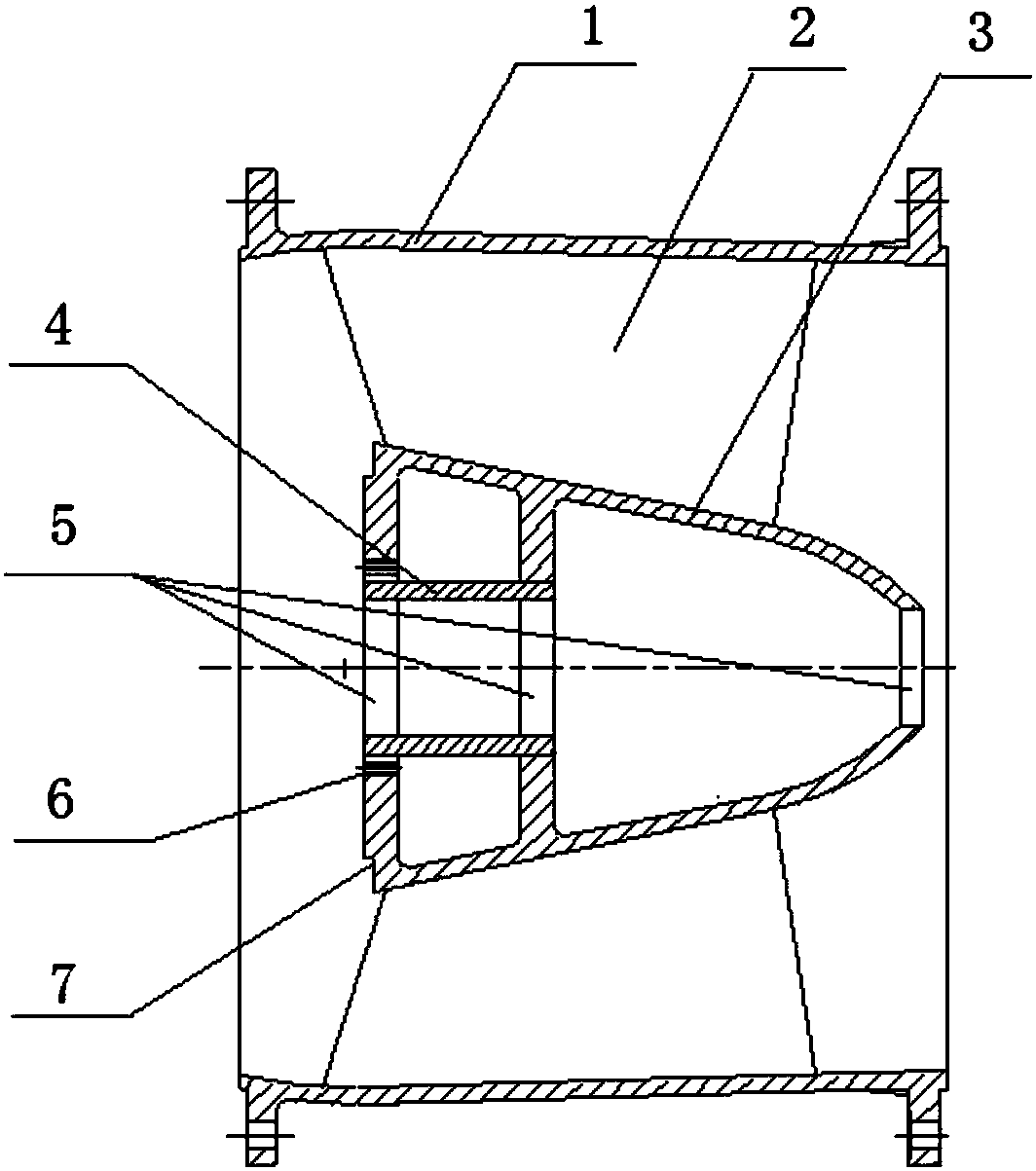
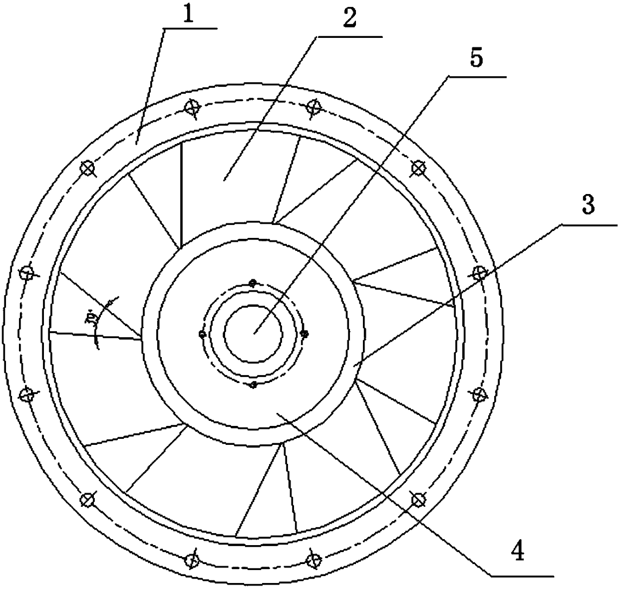
[0013] like figure 1 As shown in the figure, the guide vane body of the high-efficiency axial flow pump of the present invention includes a main shaft mounting portion, an outer wall and a guide vane, and the diameter of the main shaft mounting portion gradually decreases along the water flow direction in the axial direction, so that the front water flow pressure is lowered and is conducive to the water flow. go ahead. A first support rib and a second support rib located on the inner side are arranged at the end with the larger diameter. The first and second support rib support the pum...


PUM


Abstract

The invention discloses an efficient axial-flow pump guide blade body. The efficient axial-flow pump guide blade body comprises a main shaft mounting part, an outer wall and guide blades; the diameterof the main shaft mounting part is gradually reduced in the axial direction; a first support rib plate and a second support rib plate positioned on the inner side are arranged at the end with largerdiameter; through main shaft center holes for mounting shaft pumps are formed in the support rib plates and the end with smaller diameter of the main shaft mounting part; the first support rib plate is provided with a fixed connecting screw hole; lower rubber bearings are arranged on the end surfaces of the second support rib plate and the first support rib plate; multiple guide blades are provided, and are uniformly arranged between the main shaft mounting part and the outer wall; and the guide blades are spiral arc surfaces. The efficient axial-flow pump guide blade body is mounted behind animpeller, effectively converts water current centrifugal kinetic energy to thrust to increase the water current conveying quantity, and meanwhile, achieves stable operation parallelism.

Description

technical field [0001] The present invention particularly relates to axial flow pump rotating impeller components. Background technique [0002] Axial flow pumps are large water conservancy equipment, mainly used for farmland irrigation and water conservancy transportation. The existing axial flow pump of water conservancy conveying equipment inevitably has processing errors and installation errors in the process of production, processing and installation. Long-term operation will cause the operation of the pump shaft and impeller equipment to be unbalanced, thereby accelerating the wear of the axial flow pump and reducing the water consumption. The delivery efficiency of the flow. Ordinary axial flow pumps use the centrifugal motion of the water flow carried by the impeller to generate horizontal pressure and then generate thrust. During this process, the water flow that leaves the impeller still has a large kinetic energy in the radial centrifugal direction, which is not ...

Claims


Application Information

Patent Timeline
Patent Type & Authority Applications(China)
IPC IPC(8): F04D29/54
CPCF04D29/548
Inventor 赵玉明赵昶
Owner GAOYOU HUAN LIU PUMP IND CO LTD
Learn More