
Ventilating and cooling system installed inside indoor transformer room and method of ventilating and cooling system

A transformer room, ventilation and cooling technology, applied in the direction of ventilation system, energy recovery system for ventilation and heating, air conditioning system, etc., can solve the problems of poor ventilation and cooling effect in indoor transformer rooms, to reduce energy consumption, reduce noise, The effect of improving efficiency

Pending Publication Date: 2018-06-15
无锡赛孚电力环境控制设备有限公司 +2
View PDF0 Cites 2 Cited by
  • Summary
  • Abstract
  • Description
  • Claims
  • Application Information

AI Technical Summary

Problems solved by technology

[0005] The purpose of the present invention is to overcome the above-mentioned shortcomings of the prior art, and to solve the problem of poor ventilation and cooling effect in the indoor transformer room. In order to achieve the above-mentioned purpose, the present invention adopts the following technical solutions:

Method used


Image

  • Ventilating and cooling system installed inside indoor transformer room and method of ventilating and cooling system
  • Ventilating and cooling system installed inside indoor transformer room and method of ventilating and cooling system
  • Ventilating and cooling system installed inside indoor transformer room and method of ventilating and cooling system

Examples


Embodiment Construction

[0026] In order to describe the technical content of the present invention more clearly, the following combines Figure 1 to Figure 8 for further description.

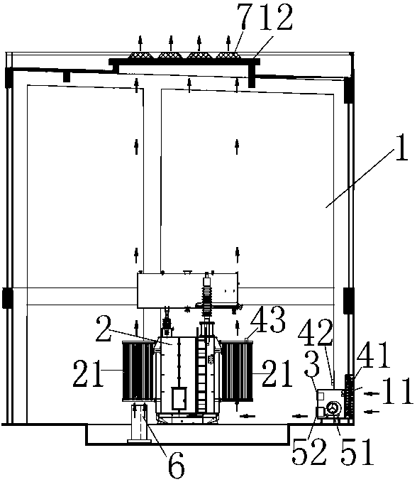
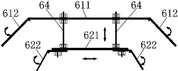
[0027] Such as figure 1 , Figure 4 , Figure 5 As shown, a ventilation and cooling system installed in an indoor transformer room, the transformer room 1 is equipped with a transformer, the transformer is equipped with a radiator 21, the air supply port 11 is located at the lower part of the side wall of the transformer room 1, and the air outlet 12 is located at the transformer room In the upper part of the room 1, the transformer room 1 is equipped with an air supply device for sending air into the transformer room 1 and an intelligent control unit 3 for controlling the air supply device; the control signal of the intelligent control unit 3 comes from a sensor; The device includes a fan 51 and an airflow adjusting device 52. The fan 51 is installed at the air outlet 11. The airflow adjusting device 52 is connect...


PUM


Abstract

The invention provides a ventilating and cooling system installed inside an indoor transformer room. A transformer is installed inside the transformer room; heat radiator is installed on the transformer; an air supply opening is positioned at the lower part of the sidewall of the transformer room; an exhaust outlet is positioned at the upper part of the transformer room; an air conveying device and an intelligent control unit are installed inside the transformer room, wherein the air conveying device is used for conveying air into the transformer room, and the intelligent control unit is usedfor controlling the air conveying device; a control signal of the intelligent control unit is from a sensor; the air conveying device comprises a fan and an air flow adjusting device; the fan is installed at the air supply opening; the air flow adjusting device is connected with an air outlet of the fan and is used for guiding the air flow sent out from the fan to the lower part of the heat radiator; the transformer room is also internally provided with an indoor air flow guiding device for changing the flowing direction of the air flow sent by the fan into an upward direction; and the indoorair flow guiding device is installed at the lower part of the heat radiator. The ventilating and cooling system provided by the invention has the advantages that (1) a ventilating system capable of effectively making the air flow pass through a region which is easily superheated is built, and the ventilation and cooling efficiency is improved; (2) the use of a roof ventilator which may generate relatively large noises is avoided, so noises are reduced; and (3) the fed fresh air directly enters the heat radiator to have heat exchange, so the energy consumption of an air supply unit is reduced.

Description

technical field [0001] The invention relates to the technical field of cooling an indoor transformer room in the electric power industry, in particular to a technology for cooling an indoor transformer room in a ventilated manner. Background technique [0002] At present, many substations are built around residential quarters and large buildings, that is, the center of electricity load. Such as Figure 8 As mentioned above, in the prior art, the air is generally taken in from the wall on one side of the transformer room and exhausted from the top. Since only one side of the three walls of the transformer room has air intake, its natural convection cannot meet the heat dissipation requirements of the transformer. In order to increase the air intake, a roof fan is often added on the roof of the transformer room for negative pressure exhaust. [0003] The application effect proves that the above-mentioned ventilation and cooling method has the following disadvantages: 1. The c...

Claims


Application Information

Patent Timeline
Patent Type & Authority Applications(China)
IPC IPC(8): F24F7/007F24F11/89F24F13/24F24F12/00
CPCF24F7/007F24F12/001F24F13/24F24F2013/247
Inventor 承方刘明涛王亚继周宏军许承
Owner 无锡赛孚电力环境控制设备有限公司
Learn More