Supercharge Your Innovation With Domain-Expert AI Agents!

Method for reducing flicker unevenness of LCD panel

A panel, uneven technology, applied in the direction of instruments, static indicators, etc., can solve the problems of affecting display uniformity, uneven flicker in the panel, uneven printing around, and achieve the effect of improving display quality and optimizing flicker unevenness.

Inactive Publication Date: 2018-06-15
SHENZHEN SPROCOMM TECH CO LTD
View PDF7 Cites 2 Cited by
  • Summary
  • Abstract
  • Description
  • Claims
  • Application Information

AI Technical Summary

Problems solved by technology

Assuming that the common electrode VCOM is 5V, and the liquid crystal display is in dot inversion mode, if the pixel voltage Vsource of a certain pixel is 0V and its adjacent pixel needs to have the same brightness as it, the pixel voltage of the adjacent pixel is 10V, but when this When the common electrode voltage of two pixels is not the same, the voltage difference is no longer the same, and then the brightness is also different, so flicker unevenness occurs
[0004] At present, the method of optimizing flicker is mainly to adjust the VCOM voltage to achieve the same voltage difference between positive and negative polarity liquid crystals; but the current LCD panel has the following problems: 1. PI printing is uneven around (physical rubbing will definitely have this problem), 2. Impurity ions are adsorbed to Ambient Affects the LCD Voltage of Ambient
The above reasons have affected the uniformity of the display in the liquid crystal box of the panel, resulting in inconsistent optimal VCOM voltages required around the panel and in the middle. After adjusting the VCOM in the middle area, the VCOM around the panel is not optimal, resulting in uneven flicker in the panel.

Method used


Image

  • Method for reducing flicker unevenness of LCD panel
  • Method for reducing flicker unevenness of LCD panel

Examples


Embodiment 1

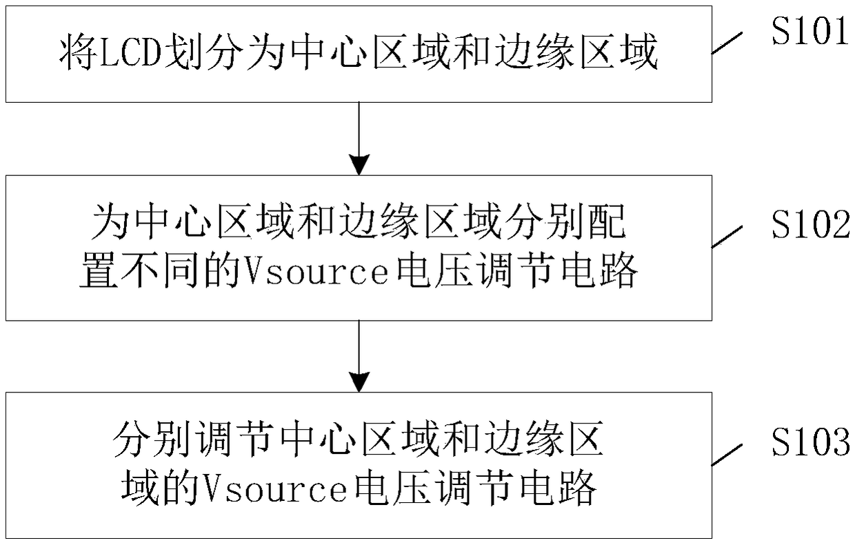
[0029] Such as figure 1 As shown, a method for reducing flicker unevenness of an LCD panel according to an embodiment of the present invention is provided, at least including the following steps:

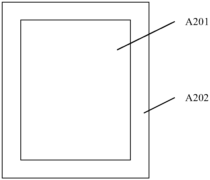
[0030] S101 as figure 2 As shown, the LCD is divided into a central area A201 and an edge area A202, the edge area A202 is an area with uneven flicker flicker, the central area is an area with uniform flicker flicker, and the edge area A202 is located at the periphery of the central area A201;

[0031] S102LCD has a built-in driver IC, the output circuit of the driver IC belonging to the central area A201 is configured as the first Vsource voltage regulation circuit, the output circuit of the driver IC belonging to the edge region is configured as the second Vsource voltage regulation circuit, the first Vsource voltage regulation circuit and the second Vsource voltage regulation circuit The two Vsource voltage adjustment circuits respectively output the first Vsource voltage and t...


PUM


Abstract

The present invention provides a method for reducing the flicker unevenness of an LCD panel. The method includes the following steps that: an LCD is divided into a center area and an edge area, wherein the edge area is an area where flicker is uneven, and the center area is an area where flicker is uniform; driving ICs are arranged in the LCD, the output circuit of the driving IC belonging to thecenter area is configured to be a first Vsource voltage adjustment circuit, and the output circuit of the driving IC belonging to the edge area is configured to be a second Vsource voltage adjustmentcircuit, the first Vsource voltage adjustment circuit and the second Vsource voltage adjustment circuit correspondingly output a first Vsource voltage and a second Vsource voltage respectively; and the first Vsource voltage adjustment circuit and the second Vsource voltage adjustment circuit are adjusted, so that the outputted first Vsource voltage and second Vsource voltage can be symmetrical relative to a Vcom voltage. According to the method of the invention, the LCD panel is divided into the two areas; the adjustment circuits are set for the driving ICs in the two areas respectively so asto adjust the voltages of the LCD panel, so that the voltages can be symmetrical relative to the Vcom voltage, and therefore, the display flicker unevenness of the LCD panel can be optimized.

Description

technical field [0001] The invention relates to the technical field of liquid crystal display screens, in particular to a method for reducing uneven flicker of an LCD panel. Background technique [0002] Because the liquid crystal display (LCD) has the characteristics of low radiation and thin thickness, it is widely used in electronic display devices such as mobile phones, televisions, and notebook computers. [0003] The liquid crystal display needs to be driven by AC when it is applied, so it needs two polarities, positive and negative, to drive the liquid crystal between each frame. The difference in brightness of the light causes flickering. A general liquid crystal panel has a common electrode, a pixel electrode, and a liquid crystal layer between the common electrode and the pixel electrode. The electrode is covered with a layer of transparent conductive film. By applying the common electrode voltage to the common electrode and applying the pixel voltage to the pixel...

Claims


Application Information

Patent Timeline
IPC IPC(8): G09G3/36
CPCG09G3/36G09G2320/0247
Inventor 王睿文周勇丛曰娜阮绪海刘星
Owner SHENZHEN SPROCOMM TECH CO LTD
Features
  • R&D
  • Intellectual Property
  • Life Sciences
  • Materials
  • Tech Scout
  • Unparalleled Data Quality
  • Higher Quality Content
  • 60% Fewer Hallucinations
Learn More