A cavity filter and debugging method

A cavity filter and debugging method technology, which is applied to waveguide-type devices, circuits, electrical components, etc., can solve problems such as high requirements for debugging personnel, large debugging workload, and difficulty in fine-tuning, achieving good debugging effects and saving manpower. Cost, easy-to-control effects

Active Publication Date: 2020-07-14
捷考奥电子(上海)有限公司
View PDF4 Cites 0 Cited by
  • Summary
  • Abstract
  • Description
  • Claims
  • Application Information

AI Technical Summary

Problems solved by technology

[0010] In order to solve the technical problems of the traditional cavity filter assembly and debugging mechanism, such as heavy workload, difficulty in fine-tuning, heavy debugging workload, many man-hours, high difficulty in debugging, high requirements for debugging personnel, and high manufacturing cost, the present invention provides a Cavity filter and debugging method, the debugging mechanism does not need to install tuning screw and lock nut on the cover, but adopts the integration of debugging mechanism, or adopts a simple method to fix the tuning element and debugging cover to form a debugging mechanism

Method used


Image

  • A cavity filter and debugging method
  • A cavity filter and debugging method
  • A cavity filter and debugging method

Examples


Embodiment Construction

[0038] The idea, specific structure and technical effects of the present invention will be further described below in conjunction with the accompanying drawings, so as to fully understand the purpose, features and effects of the present invention.

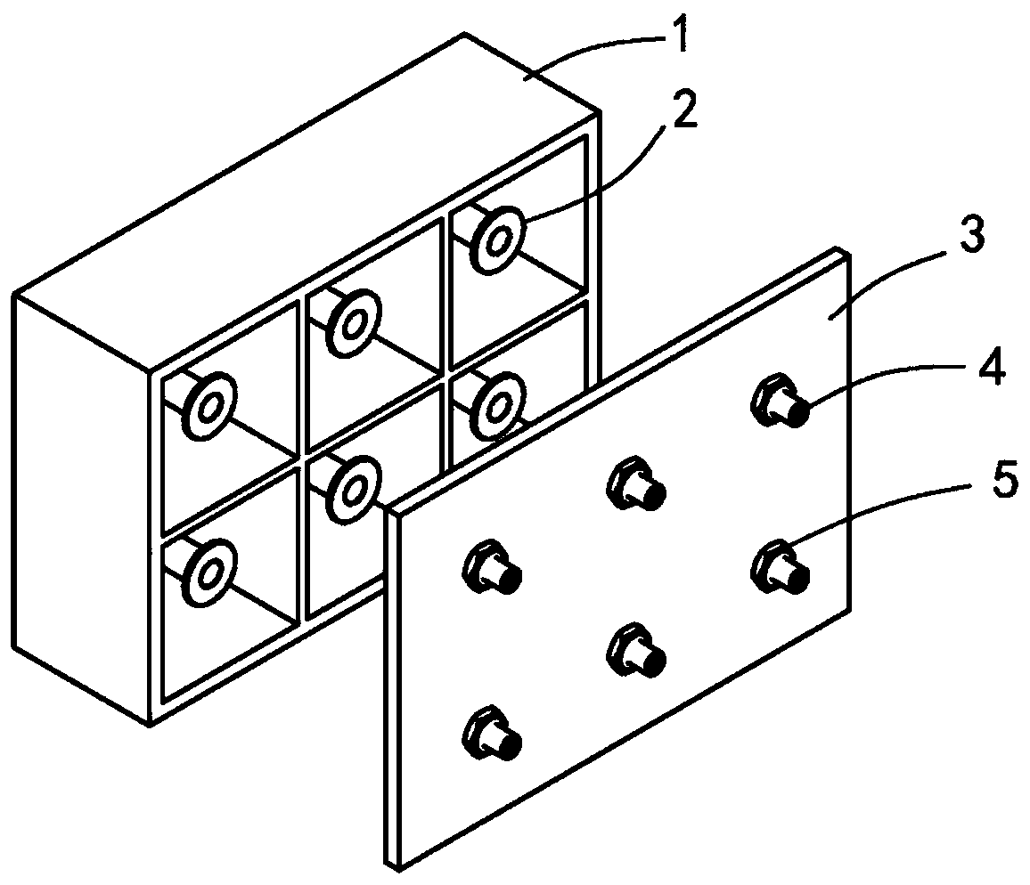
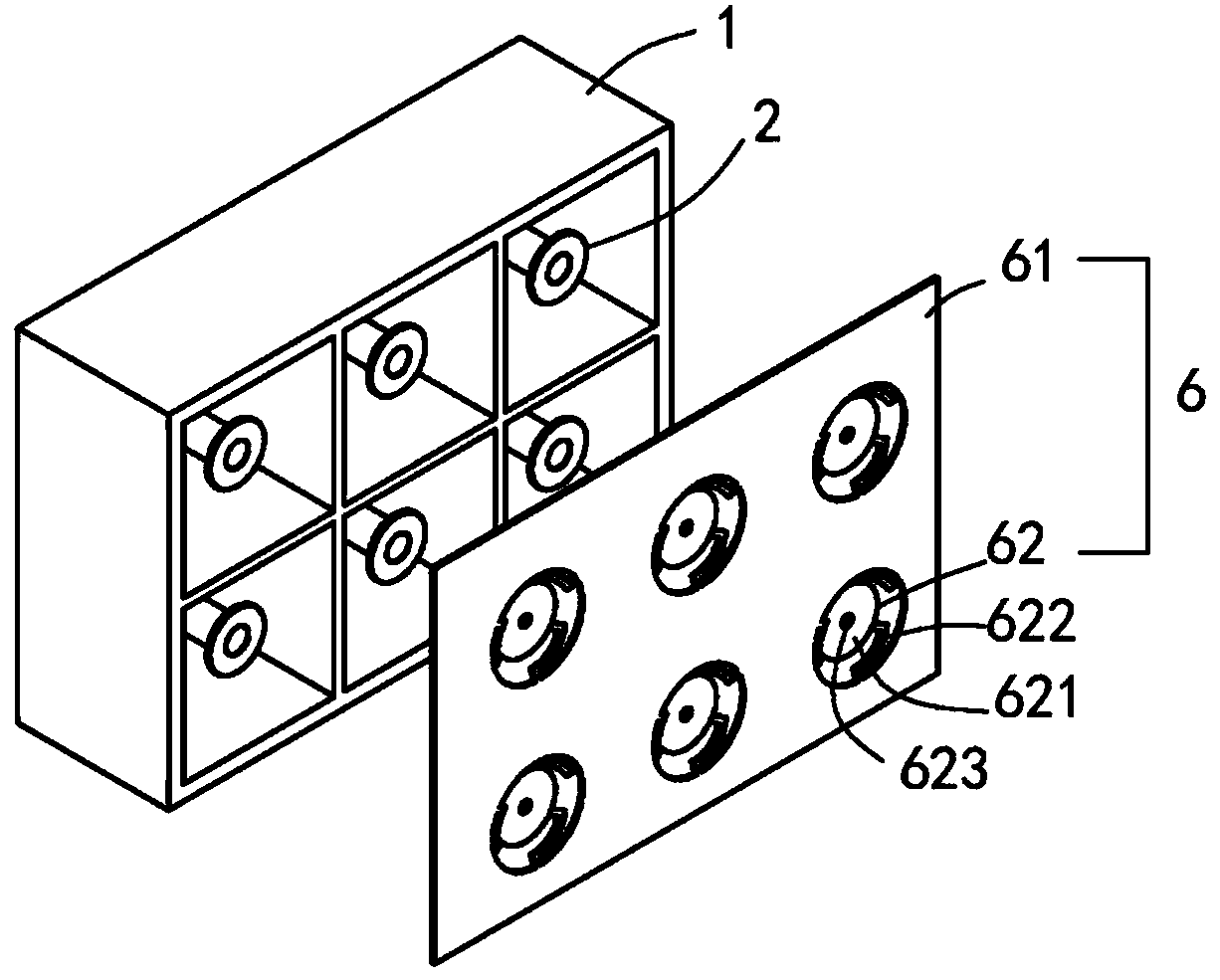
[0039] Embodiment one of the present invention, such as figure 2 , image 3 shown. The cavity filter includes a cavity 1 , several resonant rods 2 , and a debugging mechanism 6 . The upper end of the cavity 1 is open, the resonant rod 2 is installed on the inner bottom of the cavity 1, and the debugging mechanism 6 covers the upper surface of the cavity 1 and is fixed on the cavity 1 by screws.

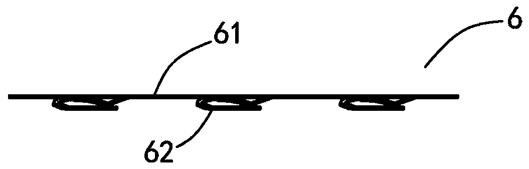
[0040]The debugging mechanism 6 includes a debugging cover 61 and several tuning elements 62 , each tuning element 62 corresponds to each resonating rod 2 one by one, and the tuning elements 62 and the debugging cover 61 are integrally formed. The tuning element 62 is a circular sheet 621 structure, three strip-shaped connecting parts ...


PUM


Abstract

The invention relates to a cavity filter and a debugging method. The cavity filter comprises a cavity with an opening at the upper end, a resonant rod arranged in the cavity and a debugging mechanism,the debugging mechanism is detachably fixed on the cavity, the debugging mechanism comprises a debugging cover plate and a tuning element, the tuning element is fixed in the hole of the debugging cover plate and corresponds to the position of the resonance rod, the tuning element can be deflected towards the inside or opposite direction of the cavity under the action of pressing or pulling force.The cavity filter does not need to be provided with a tuning screw rod and a locking nut on the cover plate, the size is smaller, the debugging structure is simpler, and fine adjustment can be realized. In the debugging process, the debugging of the cavity filter can be realized as long as the tuning element is directly pressed or pulled out, and the debugging method is simpler, faster, time-saving, good in debugging effect and low in manufacturing cost.

Description

technical field [0001] The invention relates to the field of filters, in particular to the field of cavity filters. Background technique [0002] Filters are key equipment in modern mobile communication systems and are widely used in wireless communication base stations. The cavity filter is a microwave filter with a resonant cavity structure. A cavity can be equivalent to an inductor connected in parallel with a capacitor, thereby forming a resonant stage and realizing the microwave filtering function. Because the cavity filter has the advantages of firm structure, wide frequency band, far high-end parasitic passband, small size, moderate Q value, flat amplitude-frequency characteristics in the band, stable performance, and good heat dissipation performance, it is widely used in major communication base stations Front-end filtering to filter out strong interference signals out of band. [0003] Common cavity filter structures such as figure 1 As shown, it mainly includes...

Claims


Application Information

Patent Timeline
Patent Type & Authority Patents(China)
IPC IPC(8): H01P1/208
CPCH01P1/208
Inventor 郭世奇
Owner 捷考奥电子(上海)有限公司
Why Eureka
Try Eureka